
Arguably one of the toughest looking trucks on the market, the Toyota Tundra is a popular choice for truck enthusiasts and a target for restylers. Its muscular appeal, stunning performance, and creature comforts can’t be kept a secret anymore. DJM Suspension corralled a Tundra long enough to design a 3/5 CALMAX drop kit, installed and tested it, and here is the story.
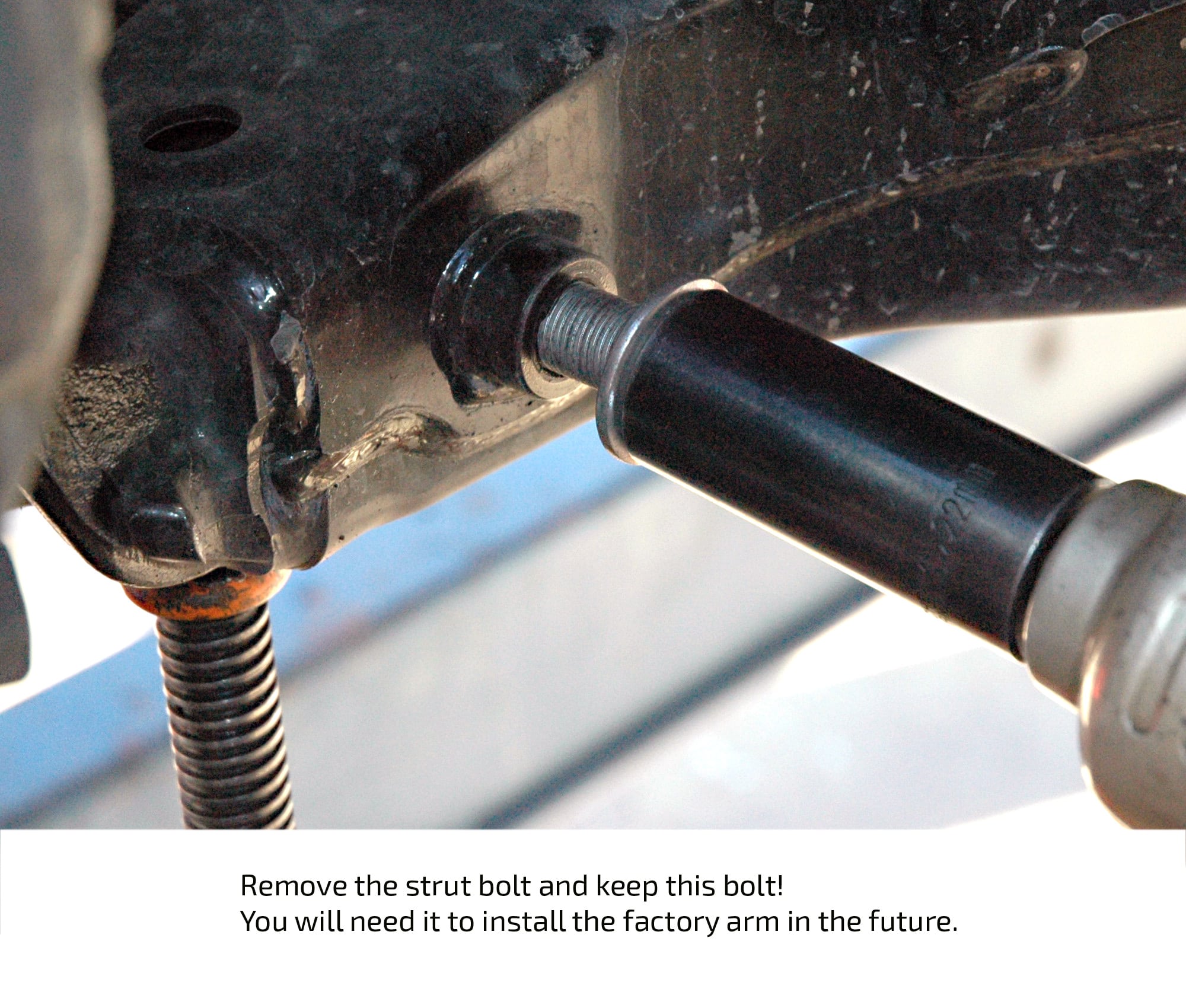
The front suspension design is a McPherson Strut type like Ford and Chevys latest platforms. The coil spring and shock absorber are integrated into one and can be removed as a unit. McPherson struts do not lend themselves to lowering with coil springs, loss of travel and ride quality issues inspired DJM to create another CALMAX CONTROL arm system for the Tundra. The arms give the Tundra a 3” drop without changing anything else. Remove and replace, couldn’t be simpler. Of course you can align the front end and use almost any wheel and tire combination you can find for a Tundra. We used the factory wheels for this install without incident.
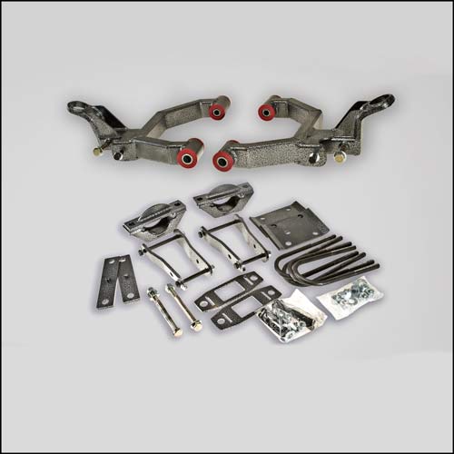
The rear is the basic truck leaf spring arrangement. DJM moved the axle from below the leaf spring to the top of the leaf. This actually lowered the rear more than the desired 5 inches and DJM designed a shackle package which will lift the rear to the proper ride height. This and the rest of the rear kit has dropped the rear a full 5” without a ride problems. You will need to run shorter shocks and DJM suggest their CALMAX SuperShox as the perfect choice for performance and ride quality.
Here is the step by step install.
toyota-tundra
Remove the tie rod end. Be careful not to damage the grease boot. [img src=http://djmsuspension.com/wp-content/flagallery/toyota-tundra/thumbs/thumbs_dsc_0011.jpg]70
Remove the strut bolt and keep this bolt! You will need it to install the factory arm in the future. [img src=http://djmsuspension.com/wp-content/flagallery/toyota-tundra/thumbs/thumbs_dsc_0012.jpg]70
To help with removing this strut bolt try placing a small jack under the control arm and use the jack to relieve pressure [img src=http://djmsuspension.com/wp-content/flagallery/toyota-tundra/thumbs/thumbs_dsc_0015.jpg]70
The easiest way to remove the ball joint is to remove the casting mounted to the spindle. You will need to keep and use these ball joints in your new Calmax control arms, as usual don't damage those ball joint boots! [img src=http://djmsuspension.com/wp-content/flagallery/toyota-tundra/thumbs/thumbs_dsc_0028.jpg]70
Using a press you can remove the factory ball joint. You need a piece of tubing with the correct diameters to push [img src=http://djmsuspension.com/wp-content/flagallery/toyota-tundra/thumbs/thumbs_dsc_0016.jpg]70
Mark the alignment before you take apart then set back after installing the Calmax arms. [img src=http://djmsuspension.com/wp-content/flagallery/toyota-tundra/thumbs/thumbs_dsc_0089.jpg]60
Install the grease zerks in the prepared holes [img src=http://djmsuspension.com/wp-content/flagallery/toyota-tundra/thumbs/thumbs_dsc_0022.jpg]70
On your lower arms DJM installed a twin tube in one side, the other side uses the factory alignment eccentric bolt. Don't forget to liberally apply grease! [img src=http://djmsuspension.com/wp-content/flagallery/toyota-tundra/thumbs/thumbs_dsc_0031.jpg]70
Install the Calmax arms in the factory mounts. Line up those alignment cams with your previous marks and tighten. (No need to over tighten here, use your best judgement) [img src=http://djmsuspension.com/wp-content/flagallery/toyota-tundra/thumbs/thumbs_dsc_0096.jpg]60
Install the strut and swaybar links with the new bolts (supplied in kit) [img src=http://djmsuspension.com/wp-content/flagallery/toyota-tundra/thumbs/thumbs_dsc_0097.jpg]60
Mount the ball joint in the casting before joining the casting to the spindle. Use the thread lock compound on the bolts [img src=http://djmsuspension.com/wp-content/flagallery/toyota-tundra/thumbs/thumbs_13.jpg]70
Remove the tie rod end so you can remove 1/4" of length from the tie rod. This allows you more adjustment with the ability to set back to stock. Tip: leave a nut on the rod when you cut, then clean up any burrs carefully and thread the nut off to finish. The tie rod end will thread on and away you go! [img src=http://djmsuspension.com/wp-content/flagallery/toyota-tundra/thumbs/thumbs_dsc_0100.jpg]60
You have threaded the tie rod end on and now mount to the spindle. [img src=http://djmsuspension.com/wp-content/flagallery/toyota-tundra/thumbs/thumbs_dsc_0041.jpg]70
These are the parts you will use to move the rear axle from below the leaf spring to on top of the leaf spring. [img src=http://djmsuspension.com/wp-content/flagallery/toyota-tundra/thumbs/thumbs_dsc_0040.jpg]60
After you have "flipped" the rear axle you will use the longer DJM Shackles to lift up your Tundra to the designed height. [img src=http://djmsuspension.com/wp-content/flagallery/toyota-tundra/thumbs/thumbs_dsc_0034.jpg]70
Now, after you support the rear of the truck properly with jack stands, using a floor jack support the rear end and [img src=http://djmsuspension.com/wp-content/flagallery/toyota-tundra/thumbs/thumbs_dsc_0044.jpg]70
You have the rear end supported now remove the leaf springs completely. Replace the factory shackles with the DJM shackles! [img src=http://djmsuspension.com/wp-content/flagallery/toyota-tundra/thumbs/thumbs_dsc_0045.jpg]70
Also you must re-position the brake line. [img src=http://djmsuspension.com/wp-content/flagallery/toyota-tundra/thumbs/thumbs_dsc_0046.jpg]70
Here you can see the brake line mount to modify. [img src=http://djmsuspension.com/wp-content/flagallery/toyota-tundra/thumbs/thumbs_dsc_0047.jpg]60
A cut-off wheel does a great job of separating the bracket from the mount. [img src=http://djmsuspension.com/wp-content/flagallery/toyota-tundra/thumbs/thumbs_dsc_0084.jpg]70
Install the leaf springs under the axle using the axle brackets, u-bolts and spring plates. Now mount the brake line bracket as shown. Reverse the mount which was cut so it rests against the bolt (not the brake line) and secure with a nylon tie wrap). [img src=http://djmsuspension.com/wp-content/flagallery/toyota-tundra/thumbs/thumbs_dsc_0106.jpg]60
The rear factory bump stops are used by installing the bracket supplied. You may want to trim the bump stop to allow more suspension travel! [img src=http://djmsuspension.com/wp-content/flagallery/toyota-tundra/thumbs/thumbs_dsc_0107.jpg]50
This images shows the rear axle kit installed, you may also notice we have not yet secured the brake line with a tie wrap, don't make the same mistake!
edges-2008-sema-sierra
[img src=http://djmsuspension.com/wp-content/flagallery/edges-2008-sema-sierra/thumbs/thumbs_dscn0457.jpg]00
[img src=http://djmsuspension.com/wp-content/flagallery/edges-2008-sema-sierra/thumbs/thumbs_dscn6535-copy.jpg]00
[img src=http://djmsuspension.com/wp-content/flagallery/edges-2008-sema-sierra/thumbs/thumbs_dscn6541.jpg]00
[img src=http://djmsuspension.com/wp-content/flagallery/edges-2008-sema-sierra/thumbs/thumbs_dscn6542.jpg]00
[img src=http://djmsuspension.com/wp-content/flagallery/edges-2008-sema-sierra/thumbs/thumbs_dscn6543.jpg]00
[img src=http://djmsuspension.com/wp-content/flagallery/edges-2008-sema-sierra/thumbs/thumbs_dscn6544.jpg]00
[img src=http://djmsuspension.com/wp-content/flagallery/edges-2008-sema-sierra/thumbs/thumbs_dscn6545.jpg]00
[img src=http://djmsuspension.com/wp-content/flagallery/edges-2008-sema-sierra/thumbs/thumbs_dscn6546.jpg]00
2007-tahoe-23-djm-calmax-lowering-kit
The most important first step with any lowering job is to measure and record the ride height. Stock irregularities will show up and you can consider how to deal with them before you tear into your project. We found the stock height to be 23 1/8th inches on this Tahoe. Note: always measure from the center of the wheel to the fender well, this will be consistent no matter what wheel and tire package you have [img src=http://djmsuspension.com/wp-content/flagallery/2007-tahoe-23-djm-calmax-lowering-kit/thumbs/thumbs_002.jpg]200Let's Get Going!
We are going to start on the rear by removing the wheels. This is a good time to mention using properly rated jack stands and a good hydraulic jack through out the project. Your safety is important! [img src=http://djmsuspension.com/wp-content/flagallery/2007-tahoe-23-djm-calmax-lowering-kit/thumbs/thumbs_003.jpg]240Cool Jack
Were using a a big hydraulic floor jack with an extension to help us manage the rear end while installing our kit [img src=http://djmsuspension.com/wp-content/flagallery/2007-tahoe-23-djm-calmax-lowering-kit/thumbs/thumbs_004.jpg]310Shocks
Loosen and remove lower shock bolts [img src=http://djmsuspension.com/wp-content/flagallery/2007-tahoe-23-djm-calmax-lowering-kit/thumbs/thumbs_005.jpg]330Swaybar
Loosen and remove the swaybar end-links [img src=http://djmsuspension.com/wp-content/flagallery/2007-tahoe-23-djm-calmax-lowering-kit/thumbs/thumbs_006.jpg]340Coil Springs
With the lower shock mount and the swaybar end-links removed you can lower the rear end with the extension jack and remove the coil springs [img src=http://djmsuspension.com/wp-content/flagallery/2007-tahoe-23-djm-calmax-lowering-kit/thumbs/thumbs_007.jpg]280Bump Stop & Coil Springs
Remove the factory bump stops and set aside for modification later. Replace the factory spring with the DJM 3" coil spring. Also you can install the shock extenders now [img src=http://djmsuspension.com/wp-content/flagallery/2007-tahoe-23-djm-calmax-lowering-kit/thumbs/thumbs_008.jpg]300Spring Comparison
Here is how the factory coil spring (left) stacks up against the DJM engineered lowering spring. It's important to note that simply shortening a coil by 1" lets say will result in a 1" drop, most likely not. There are many factors at work with automotive springs so be very careful if you are tempted to save a buck and cut your coils! [img src=http://djmsuspension.com/wp-content/flagallery/2007-tahoe-23-djm-calmax-lowering-kit/thumbs/thumbs_009.jpg]300Modify Bump Stop
Shorten the factory bump stop by cutting off material and installing in it's original location. [img src=http://djmsuspension.com/wp-content/flagallery/2007-tahoe-23-djm-calmax-lowering-kit/thumbs/thumbs_010.jpg]330Rear Shocks
Using your jack supporting the rear end to lift the rear end up so you can attach the rear shocks to the new shock extenders [img src=http://djmsuspension.com/wp-content/flagallery/2007-tahoe-23-djm-calmax-lowering-kit/thumbs/thumbs_011.jpg]290
[img src=http://djmsuspension.com/wp-content/flagallery/2007-tahoe-23-djm-calmax-lowering-kit/thumbs/thumbs_012.jpg]300New Mounting
Drill out two holes for the pivot bushing mount on the left (drivers side) and install the pivot bushing and bracket with the new hardware provided [img src=http://djmsuspension.com/wp-content/flagallery/2007-tahoe-23-djm-calmax-lowering-kit/thumbs/thumbs_013.jpg]310Endlinks
Install your new DJM swaybar end-links. It is not necessary to tighten too much, in fact it will cause the links to bind and damage the urethane bushings. So tighten until there is no play and maybe a quarter turn more. And as with all fasteners check them later after you have driven for a while to make sure they are till tight! [img src=http://djmsuspension.com/wp-content/flagallery/2007-tahoe-23-djm-calmax-lowering-kit/thumbs/thumbs_014.jpg]310Wow!
Notice the difference between the original swaybar links and where the sway mounts after the lowering springs are installed. [img src=http://djmsuspension.com/wp-content/flagallery/2007-tahoe-23-djm-calmax-lowering-kit/thumbs/thumbs_015.jpg]280Trailing Arm Brackets
The rear trailing arms locating the axle need to be moved down a little to keep from binding and making contact. The brackets in the DJM kit accomplish this by moving the mounting point to the axle down away from trouble. [img src=http://djmsuspension.com/wp-content/flagallery/2007-tahoe-23-djm-calmax-lowering-kit/thumbs/thumbs_016.jpg]330Measuring
With everything installed in the rear you can take a measurement and see where you are. We got a measurement of 19 3/4" after the kit was installed, a little more than three inchs [img src=http://djmsuspension.com/wp-content/flagallery/2007-tahoe-23-djm-calmax-lowering-kit/thumbs/thumbs_017.jpg]320Moving to the Front
As always we get a before measurement for a baseline. This time we measure 20 1/4" [img src=http://djmsuspension.com/wp-content/flagallery/2007-tahoe-23-djm-calmax-lowering-kit/thumbs/thumbs_018.jpg]340Tie Rod
And after we have safely supported the Tahoe with adequate jack stands we remove the wheels and go to work removing the tie rod ends [img src=http://djmsuspension.com/wp-content/flagallery/2007-tahoe-23-djm-calmax-lowering-kit/thumbs/thumbs_019.jpg]330Lower Ball Joint
With the help of a bottle jack we are supporting the lower control arm. Next is to loosen but not remove the nut on the lower ball joint and give a good whack on the casting (spindle) NOT THE BALL JOINT to break the taper [img src=http://djmsuspension.com/wp-content/flagallery/2007-tahoe-23-djm-calmax-lowering-kit/thumbs/thumbs_020.jpg]330Separating the Control Arm and Spindle
Letting the jack do the heavy lifting move the control arm up and free the spindle from the lower ball joint. Be careful with the spindle so the brake line is not compromised [img src=http://djmsuspension.com/wp-content/flagallery/2007-tahoe-23-djm-calmax-lowering-kit/thumbs/thumbs_021.jpg]320Strut
Loosen and remove the bolts attaching the strut to the lower control arm [img src=http://djmsuspension.com/wp-content/flagallery/2007-tahoe-23-djm-calmax-lowering-kit/thumbs/thumbs_022.jpg]290Swaybar
Loosen and remove the end-link connecting the swaybar to the control arm. If your interested in high performance swaybars check out the Calmax Swaybars for 07-11 Tahoes in DJM/Applications [img src=http://djmsuspension.com/wp-content/flagallery/2007-tahoe-23-djm-calmax-lowering-kit/thumbs/thumbs_023.jpg]310Pivot Bolts
Loosen and remove the factory pivot bolts on the lower control arms [img src=http://djmsuspension.com/wp-content/flagallery/2007-tahoe-23-djm-calmax-lowering-kit/thumbs/thumbs_024.jpg]290Remove the arm
Now you can pull the lower arm out of the mounting points [img src=http://djmsuspension.com/wp-content/flagallery/2007-tahoe-23-djm-calmax-lowering-kit/thumbs/thumbs_025.jpg]360Compare
A quick look at the Calmax and the factory arms side by side [img src=http://djmsuspension.com/wp-content/flagallery/2007-tahoe-23-djm-calmax-lowering-kit/thumbs/thumbs_026.jpg]310Install grease zerks
To avoid damage during shipping, the grease zerks are installed just before installation. [img src=http://djmsuspension.com/wp-content/flagallery/2007-tahoe-23-djm-calmax-lowering-kit/thumbs/thumbs_027.jpg]270Lots of Grease
Don't be afraid to use plenty of grease. It's alot easier to apply now before you install the part. Make sure the inner (twin tube) tube is liberally greased up and shoot grease through the zerk. be sure to also grease the shoulders of the urethane bushings. Don't forget to grease the ball joint!!! [img src=http://djmsuspension.com/wp-content/flagallery/2007-tahoe-23-djm-calmax-lowering-kit/thumbs/thumbs_028.jpg]270Install the Calmax Control Arms
Place the Calmax in the factory mounting points install the bolts and using the nylon locknuts provided, tighten. Of course you can over-tighten these, be careful. They should be no "slop" and tight. Do not squeeze the bushings, they will squeak and wear prematurely [img src=http://djmsuspension.com/wp-content/flagallery/2007-tahoe-23-djm-calmax-lowering-kit/thumbs/thumbs_029.jpg]260Strut
Attach the factory strut just like the factory arm [img src=http://djmsuspension.com/wp-content/flagallery/2007-tahoe-23-djm-calmax-lowering-kit/thumbs/thumbs_030.jpg]270Lower Ball Joint
And using the bottle jack, lift the arm to gain clearance and lower the ball joint into the spindle and tighten [img src=http://djmsuspension.com/wp-content/flagallery/2007-tahoe-23-djm-calmax-lowering-kit/thumbs/thumbs_031.jpg]270Swaybar
Attach the swaybar end-link to the lower control arm [img src=http://djmsuspension.com/wp-content/flagallery/2007-tahoe-23-djm-calmax-lowering-kit/thumbs/thumbs_032.jpg]280Tie Rod
Install the tie rod end to the spindle. Install the wheels and your ready to roll [img src=http://djmsuspension.com/wp-content/flagallery/2007-tahoe-23-djm-calmax-lowering-kit/thumbs/thumbs_033.jpg]330Final Inspection
Check over everything you have done to make sure nothing is loose. Go for a short test drive and measure the front. We got 18" for a drop of 2 1/4". When you sure everything is buttoned up get a professional alignment and enjoy you new lowered stance
2007-silverado-36-djm-calmax-drop-kit
The best way to begin any lowering job is with good starting measurements. The most accurate way to do this is to measure from the center of the wheel to the fender lip. No matter what wheel and tire combination you use this relationship remains the same. So if you install the lowering kit and upgrade your wheels and tires it won't affect your after measurement! Here we measured 22 1/4' [img src=http://djmsuspension.com/wp-content/flagallery/2007-silverado-36-djm-calmax-drop-kit/thumbs/thumbs_102.jpg]990Proper Foundation
The first step of course is to remove the wheels. Having the proper jacks and jack stands makes the job easier and much safer. Make sure your jack stands are rated for the weight of your vehicle and a good hydraulic floor jack and bottle jack are indispensable [img src=http://djmsuspension.com/wp-content/flagallery/2007-silverado-36-djm-calmax-drop-kit/thumbs/thumbs_103.jpg]1020Tie Rod End
Lets get going by removing the tie rod end [img src=http://djmsuspension.com/wp-content/flagallery/2007-silverado-36-djm-calmax-drop-kit/thumbs/thumbs_104.jpg]980Lower Ball Joint
Loosen and remove the lower ball joint nut [img src=http://djmsuspension.com/wp-content/flagallery/2007-silverado-36-djm-calmax-drop-kit/thumbs/thumbs_105.jpg]980Safety
Notice the jack stand under the frame and the bottle jack ready to go! [img src=http://djmsuspension.com/wp-content/flagallery/2007-silverado-36-djm-calmax-drop-kit/thumbs/thumbs_106.jpg]950Separating the Lower Control Arm from the Spindle
Using the bottle jack to lift the control arm up carefully pull the spindle down and away from the lower ball joint [img src=http://djmsuspension.com/wp-content/flagallery/2007-silverado-36-djm-calmax-drop-kit/thumbs/thumbs_107.jpg]950Struts
Now you can loosen and remove the bolts securing the struts to the lower control arms [img src=http://djmsuspension.com/wp-content/flagallery/2007-silverado-36-djm-calmax-drop-kit/thumbs/thumbs_108.jpg]990Pivot Bolts
Loosen and remove the pivot bolts and your ready to pull the factory lower control arm away from the mounts [img src=http://djmsuspension.com/wp-content/flagallery/2007-silverado-36-djm-calmax-drop-kit/thumbs/thumbs_109.jpg]930Calmax Arms
Here are the Calmax arms ready to prepare for installation. Note: Use the installation helper to record your information [img src=http://djmsuspension.com/wp-content/flagallery/2007-silverado-36-djm-calmax-drop-kit/thumbs/thumbs_110.jpg]940New Nuts
These new nylon lock nuts are to be used on the pivot bolts when the arms are installed [img src=http://djmsuspension.com/wp-content/flagallery/2007-silverado-36-djm-calmax-drop-kit/thumbs/thumbs_111.jpg]870Pivot Grease Points
The zerks are not installed at the factory because they have been found to be broken off during shipping. They are easy to install, simply screw them in! [img src=http://djmsuspension.com/wp-content/flagallery/2007-silverado-36-djm-calmax-drop-kit/thumbs/thumbs_112.jpg]850Ball Joint Grease Point
And again screw the ball joint zerk in place [img src=http://djmsuspension.com/wp-content/flagallery/2007-silverado-36-djm-calmax-drop-kit/thumbs/thumbs_113.jpg]830Grease it up
Apply grease through the zerks to make sure the passages are clear [img src=http://djmsuspension.com/wp-content/flagallery/2007-silverado-36-djm-calmax-drop-kit/thumbs/thumbs_114.jpg]840Inner Sleeve
Liberally apply grease to the inner sleeve and insert making sure there are no burrs. Also grease up the shoulders of the urethane bushings before you install [img src=http://djmsuspension.com/wp-content/flagallery/2007-silverado-36-djm-calmax-drop-kit/thumbs/thumbs_115.jpg]790Ready to Install
Install the new Calmax control arms in the same mounting points as the factory arms [img src=http://djmsuspension.com/wp-content/flagallery/2007-silverado-36-djm-calmax-drop-kit/thumbs/thumbs_116.jpg]810Arms in Place
Using the factory bolts and the supplied locknuts secure the arms. Hand tighten only at this point [img src=http://djmsuspension.com/wp-content/flagallery/2007-silverado-36-djm-calmax-drop-kit/thumbs/thumbs_117.jpg]830Mounting the Spindle
Using that trusty bottle jack maneuver the lower arm up enough to allow the spindle to receive the lower ball joint [img src=http://djmsuspension.com/wp-content/flagallery/2007-silverado-36-djm-calmax-drop-kit/thumbs/thumbs_118.jpg]790Strut
Tighten the lower ball joint and mount the strut in position and tighten the strut bolts [img src=http://djmsuspension.com/wp-content/flagallery/2007-silverado-36-djm-calmax-drop-kit/thumbs/thumbs_119.jpg]810Sway-bars
Attach the swaybar to the Calmax control arm and tighten the pivot points (don't over-tighten). If your interested in High Performance swaybar systems check out the Calmax Swaybay setups for trucks and SUV's! [img src=http://djmsuspension.com/wp-content/flagallery/2007-silverado-36-djm-calmax-drop-kit/thumbs/thumbs_120.jpg]780Upper Arms
We start off with removing the ABS bracket and brake clip and unplugging the ABS wire [img src=http://djmsuspension.com/wp-content/flagallery/2007-silverado-36-djm-calmax-drop-kit/thumbs/thumbs_121.jpg]850Pivot Points
Remove the nuts from the pivot bolts [img src=http://djmsuspension.com/wp-content/flagallery/2007-silverado-36-djm-calmax-drop-kit/thumbs/thumbs_122.jpg]900Alignment Cams
As you remove the pivot bolts be careful to retain and arrange the alignment cams so you can install them again in the same order and position as you removed them [img src=http://djmsuspension.com/wp-content/flagallery/2007-silverado-36-djm-calmax-drop-kit/thumbs/thumbs_123.jpg]820Ball Joint
Loosen and remove the upper ball joint nut, break the taper between the ball joint and the spindle and remove the upper control arm [img src=http://djmsuspension.com/wp-content/flagallery/2007-silverado-36-djm-calmax-drop-kit/thumbs/thumbs_124.jpg]910Upper Control Arms
Compare the factory arm (left) with the Calmax arm. Notice the change in the ball joint angle to optimize the angle at the new ride height [img src=http://djmsuspension.com/wp-content/flagallery/2007-silverado-36-djm-calmax-drop-kit/thumbs/thumbs_126.jpg]970Grease it up!
Just like the lower arm liberally apply grease to the pivot points and ball joints after you install the grease zerks! [img src=http://djmsuspension.com/wp-content/flagallery/2007-silverado-36-djm-calmax-drop-kit/thumbs/thumbs_127.jpg]880The upper Arms in
Push the upper arm into place, and using the factory bolts and alignment cams in the order and position you removed them. assemble and tighten [img src=http://djmsuspension.com/wp-content/flagallery/2007-silverado-36-djm-calmax-drop-kit/thumbs/thumbs_128.jpg]840Upper Ball Joint
Insert the upper ball joint into spindle. [img src=http://djmsuspension.com/wp-content/flagallery/2007-silverado-36-djm-calmax-drop-kit/thumbs/thumbs_129.jpg]840What are those washers for?
The hole in the ball joint stud for the cotter pin to go through requires the two washers on the nut side so you have proper alignment for the cotter pin [img src=http://djmsuspension.com/wp-content/flagallery/2007-silverado-36-djm-calmax-drop-kit/thumbs/thumbs_130.jpg]840Finished!
Here is what the installation looks like completed [img src=http://djmsuspension.com/wp-content/flagallery/2007-silverado-36-djm-calmax-drop-kit/thumbs/thumbs_131.jpg]1050Lowered Measurement
Wheels back on and setting on it's own weight were getting a reading of 19". A drop of 3 1/4" [img src=http://djmsuspension.com/wp-content/flagallery/2007-silverado-36-djm-calmax-drop-kit/thumbs/thumbs_132.jpg]1320Yikes the hangers are welded on!
In 2007 Chevy started welding the leaf spring eye hangers to the frame of Silverado's full time. The gas tank and exhaust system make removing this bolt a giant pain in the #*#. We decided not to remove the leaf spring [img src=http://djmsuspension.com/wp-content/flagallery/2007-silverado-36-djm-calmax-drop-kit/thumbs/thumbs_135.jpg]1170You need Jack!
Just like the front were using the jack stands to support the frame in the rear, but we have changed from a bottle jack to a hydraulic floor jack with an extension. This baby has wheels which allow us to move the rear end around to help us install the rear kit! [img src=http://djmsuspension.com/wp-content/flagallery/2007-silverado-36-djm-calmax-drop-kit/thumbs/thumbs_133.jpg]1250The Axle
So we move back to the axle and remove the U-bolts and the spring center bolts, after we clamp the leaf spring pack [img src=http://djmsuspension.com/wp-content/flagallery/2007-silverado-36-djm-calmax-drop-kit/thumbs/thumbs_134.jpg]1190Reverse the pin
We install the spring center pin upside down with the pin (head) up on top [img src=http://djmsuspension.com/wp-content/flagallery/2007-silverado-36-djm-calmax-drop-kit/thumbs/thumbs_136.jpg]1210Brake Lines
Remove the brake line and e-brake brackets from the frame so they are free to move with the rear end [img src=http://djmsuspension.com/wp-content/flagallery/2007-silverado-36-djm-calmax-drop-kit/thumbs/thumbs_137.jpg]1400Floor Jack Advantage
Because the floor jack has wheels we can push the rear end sideways to allow us to drop the leaf spring below the axle without having to totally remove it [img src=http://djmsuspension.com/wp-content/flagallery/2007-silverado-36-djm-calmax-drop-kit/thumbs/thumbs_138.jpg]1380Same Thing
Same for the other side [img src=http://djmsuspension.com/wp-content/flagallery/2007-silverado-36-djm-calmax-drop-kit/thumbs/thumbs_139.jpg]1330Axle Brackets
The axle brackets are located over the spring center bolts and the axle is positioned in the axle brackets [img src=http://djmsuspension.com/wp-content/flagallery/2007-silverado-36-djm-calmax-drop-kit/thumbs/thumbs_140.jpg]1350Pinion Angle
Now is when you want set the pinion angle. By rotating the axle you have total control over this procedure [img src=http://djmsuspension.com/wp-content/flagallery/2007-silverado-36-djm-calmax-drop-kit/thumbs/thumbs_141.jpg]1460Rear Assembly
Here is the axle on top of the leaf springs with the top plate, U-bolts and spring plate all working together to set the pinion and secure the axle [img src=http://djmsuspension.com/wp-content/flagallery/2007-silverado-36-djm-calmax-drop-kit/thumbs/thumbs_142.jpg]1370Bump Stop
It's time to remove the factory bump stop [img src=http://djmsuspension.com/wp-content/flagallery/2007-silverado-36-djm-calmax-drop-kit/thumbs/thumbs_143.jpg]1400Bump Stop Bracket
We used a plasma cutter to remove the factory bump stop bracket [img src=http://djmsuspension.com/wp-content/flagallery/2007-silverado-36-djm-calmax-drop-kit/thumbs/thumbs_144.jpg]1380New Bump Stop
Using the drill bit and thread tap provided in the lowering kit we drilled and created threads in the hole and installed the shorter urethane bump stop [img src=http://djmsuspension.com/wp-content/flagallery/2007-silverado-36-djm-calmax-drop-kit/thumbs/thumbs_146.jpg]1410Shackle Hanger
it is necessary to remove the factory shackle hanger (or mount). The factory part is on the left and we will replace it with the new DJM bracket which inverts the shackle mount [img src=http://djmsuspension.com/wp-content/flagallery/2007-silverado-36-djm-calmax-drop-kit/thumbs/thumbs_147.jpg]1480Your Choice
Using the DJM shackle that is longer than factory will yield either a 4 or a 5" drop. If you use the shorter factory shackle you will get a 6" drop! [img src=http://djmsuspension.com/wp-content/flagallery/2007-silverado-36-djm-calmax-drop-kit/thumbs/thumbs_148.jpg]1570The 6
This is the 6" combination [img src=http://djmsuspension.com/wp-content/flagallery/2007-silverado-36-djm-calmax-drop-kit/thumbs/thumbs_149.jpg]1440The last big blow
Here we are beating away the last piece of the original factory shackle mount [img src=http://djmsuspension.com/wp-content/flagallery/2007-silverado-36-djm-calmax-drop-kit/thumbs/thumbs_150.jpg]1460New Mounting Bracket
The new shackle bracket is secured in place and the leaf spring attached to the shackle. That's it! [img src=http://djmsuspension.com/wp-content/flagallery/2007-silverado-36-djm-calmax-drop-kit/thumbs/thumbs_151.jpg]2030The Stance!
This is the 3/6 look. You can also do a 3/5, 4/6, or a 4/7 kit on these late model Silverado's. It's all your choice!
2006-toyota-tacoma-34-djm-kit
[img src=http://djmsuspension.com/wp-content/flagallery/2006-toyota-tacoma-34-djm-kit/thumbs/thumbs_002.jpg]470
[img src=http://djmsuspension.com/wp-content/flagallery/2006-toyota-tacoma-34-djm-kit/thumbs/thumbs_003.jpg]490
[img src=http://djmsuspension.com/wp-content/flagallery/2006-toyota-tacoma-34-djm-kit/thumbs/thumbs_004.jpg]470
[img src=http://djmsuspension.com/wp-content/flagallery/2006-toyota-tacoma-34-djm-kit/thumbs/thumbs_005.jpg]370
[img src=http://djmsuspension.com/wp-content/flagallery/2006-toyota-tacoma-34-djm-kit/thumbs/thumbs_007.jpg]370
[img src=http://djmsuspension.com/wp-content/flagallery/2006-toyota-tacoma-34-djm-kit/thumbs/thumbs_008.jpg]400
[img src=http://djmsuspension.com/wp-content/flagallery/2006-toyota-tacoma-34-djm-kit/thumbs/thumbs_009.jpg]350
[img src=http://djmsuspension.com/wp-content/flagallery/2006-toyota-tacoma-34-djm-kit/thumbs/thumbs_010.jpg]330
[img src=http://djmsuspension.com/wp-content/flagallery/2006-toyota-tacoma-34-djm-kit/thumbs/thumbs_012.jpg]310
[img src=http://djmsuspension.com/wp-content/flagallery/2006-toyota-tacoma-34-djm-kit/thumbs/thumbs_013.jpg]280
[img src=http://djmsuspension.com/wp-content/flagallery/2006-toyota-tacoma-34-djm-kit/thumbs/thumbs_014.jpg]290
[img src=http://djmsuspension.com/wp-content/flagallery/2006-toyota-tacoma-34-djm-kit/thumbs/thumbs_015.jpg]310
[img src=http://djmsuspension.com/wp-content/flagallery/2006-toyota-tacoma-34-djm-kit/thumbs/thumbs_016.jpg]290
[img src=http://djmsuspension.com/wp-content/flagallery/2006-toyota-tacoma-34-djm-kit/thumbs/thumbs_018.jpg]270
[img src=http://djmsuspension.com/wp-content/flagallery/2006-toyota-tacoma-34-djm-kit/thumbs/thumbs_019.jpg]350
[img src=http://djmsuspension.com/wp-content/flagallery/2006-toyota-tacoma-34-djm-kit/thumbs/thumbs_021.jpg]300
[img src=http://djmsuspension.com/wp-content/flagallery/2006-toyota-tacoma-34-djm-kit/thumbs/thumbs_022.jpg]280
[img src=http://djmsuspension.com/wp-content/flagallery/2006-toyota-tacoma-34-djm-kit/thumbs/thumbs_023.jpg]280
[img src=http://djmsuspension.com/wp-content/flagallery/2006-toyota-tacoma-34-djm-kit/thumbs/thumbs_024.jpg]260
[img src=http://djmsuspension.com/wp-content/flagallery/2006-toyota-tacoma-34-djm-kit/thumbs/thumbs_026.jpg]280
[img src=http://djmsuspension.com/wp-content/flagallery/2006-toyota-tacoma-34-djm-kit/thumbs/thumbs_028.jpg]290
[img src=http://djmsuspension.com/wp-content/flagallery/2006-toyota-tacoma-34-djm-kit/thumbs/thumbs_030.jpg]270
[img src=http://djmsuspension.com/wp-content/flagallery/2006-toyota-tacoma-34-djm-kit/thumbs/thumbs_031.jpg]300
[img src=http://djmsuspension.com/wp-content/flagallery/2006-toyota-tacoma-34-djm-kit/thumbs/thumbs_032.jpg]310
[img src=http://djmsuspension.com/wp-content/flagallery/2006-toyota-tacoma-34-djm-kit/thumbs/thumbs_033.jpg]310
[img src=http://djmsuspension.com/wp-content/flagallery/2006-toyota-tacoma-34-djm-kit/thumbs/thumbs_034.jpg]250
[img src=http://djmsuspension.com/wp-content/flagallery/2006-toyota-tacoma-34-djm-kit/thumbs/thumbs_035.jpg]250
[img src=http://djmsuspension.com/wp-content/flagallery/2006-toyota-tacoma-34-djm-kit/thumbs/thumbs_036.jpg]260
[img src=http://djmsuspension.com/wp-content/flagallery/2006-toyota-tacoma-34-djm-kit/thumbs/thumbs_037.jpg]270
[img src=http://djmsuspension.com/wp-content/flagallery/2006-toyota-tacoma-34-djm-kit/thumbs/thumbs_039.jpg]300
[img src=http://djmsuspension.com/wp-content/flagallery/2006-toyota-tacoma-34-djm-kit/thumbs/thumbs_040.jpg]310
[img src=http://djmsuspension.com/wp-content/flagallery/2006-toyota-tacoma-34-djm-kit/thumbs/thumbs_041.jpg]320
[img src=http://djmsuspension.com/wp-content/flagallery/2006-toyota-tacoma-34-djm-kit/thumbs/thumbs_042.jpg]310
[img src=http://djmsuspension.com/wp-content/flagallery/2006-toyota-tacoma-34-djm-kit/thumbs/thumbs_043.jpg]330
[img src=http://djmsuspension.com/wp-content/flagallery/2006-toyota-tacoma-34-djm-kit/thumbs/thumbs_044.jpg]280
[img src=http://djmsuspension.com/wp-content/flagallery/2006-toyota-tacoma-34-djm-kit/thumbs/thumbs_045.jpg]320
[img src=http://djmsuspension.com/wp-content/flagallery/2006-toyota-tacoma-34-djm-kit/thumbs/thumbs_046.jpg]270
[img src=http://djmsuspension.com/wp-content/flagallery/2006-toyota-tacoma-34-djm-kit/thumbs/thumbs_049.jpg]320
[img src=http://djmsuspension.com/wp-content/flagallery/2006-toyota-tacoma-34-djm-kit/thumbs/thumbs_050.jpg]390
[img src=http://djmsuspension.com/wp-content/flagallery/2006-toyota-tacoma-34-djm-kit/thumbs/thumbs_051.jpg]380
[img src=http://djmsuspension.com/wp-content/flagallery/2006-toyota-tacoma-34-djm-kit/thumbs/thumbs_052.jpg]500
[img src=http://djmsuspension.com/wp-content/flagallery/2006-toyota-tacoma-34-djm-kit/thumbs/thumbs_053.jpg]530
[img src=http://djmsuspension.com/wp-content/flagallery/2006-toyota-tacoma-34-djm-kit/thumbs/thumbs_054.jpg]630
[img src=http://djmsuspension.com/wp-content/flagallery/2006-toyota-tacoma-34-djm-kit/thumbs/thumbs_055.jpg]610
[img src=http://djmsuspension.com/wp-content/flagallery/2006-toyota-tacoma-34-djm-kit/thumbs/thumbs_056.jpg]560
[img src=http://djmsuspension.com/wp-content/flagallery/2006-toyota-tacoma-34-djm-kit/thumbs/thumbs_057.jpg]610
[img src=http://djmsuspension.com/wp-content/flagallery/2006-toyota-tacoma-34-djm-kit/thumbs/thumbs_058.jpg]700
[img src=http://djmsuspension.com/wp-content/flagallery/2006-toyota-tacoma-34-djm-kit/thumbs/thumbs_059.jpg]730
[img src=http://djmsuspension.com/wp-content/flagallery/2006-toyota-tacoma-34-djm-kit/thumbs/thumbs_064.jpg]790
[img src=http://djmsuspension.com/wp-content/flagallery/2006-toyota-tacoma-34-djm-kit/thumbs/thumbs_075.jpg]650
[img src=http://djmsuspension.com/wp-content/flagallery/2006-toyota-tacoma-34-djm-kit/thumbs/thumbs_076.jpg]630
[img src=http://djmsuspension.com/wp-content/flagallery/2006-toyota-tacoma-34-djm-kit/thumbs/thumbs_077a.jpg]1180
2004-4wd-avalanche
It's important to measure the stock ride height before you begin. The most accurate method is to measure from the center of your wheel to the fender lip. This distance won't change if you upgrade your wheel and tires, and will give you the real drop figures after your done! It will also show any irregularities in the factory ride height. [img src=http://djmsuspension.com/wp-content/flagallery/2004-4wd-avalanche/thumbs/thumbs_002.jpg]220Proper Foundation
As important as establishing stock ride height is, safety is more important. Having the proper jacks and jack stands makes the job easier and much safer. Make sure your jack stands are rated for the weight of your vehicle and a good hydraulic floor jack and bottle jack are indispensable [img src=http://djmsuspension.com/wp-content/flagallery/2004-4wd-avalanche/thumbs/thumbs_003.jpg]230Tie Rod
Loosen and removing the tie rod end is the best way to start. [img src=http://djmsuspension.com/wp-content/flagallery/2004-4wd-avalanche/thumbs/thumbs_004.jpg]240Here's A Tip!
Making a simple hanger to use to hang spindles or brake calipers out of the way during installations is a very good idea [img src=http://djmsuspension.com/wp-content/flagallery/2004-4wd-avalanche/thumbs/thumbs_005.jpg]220Brake Line & Caliper
Loosen and remove the 10mm bolts that secure the brake line to the upper control arm. Also loosen and remove the cap head screws which fix the caliper to the steering knuckle [img src=http://djmsuspension.com/wp-content/flagallery/2004-4wd-avalanche/thumbs/thumbs_006.jpg]240Your Cool Hanger
Now you can use that cool hanger you made to hang to brake caliper out of the way and not damage the brake line! [img src=http://djmsuspension.com/wp-content/flagallery/2004-4wd-avalanche/thumbs/thumbs_007.jpg]220Torsion Bar
Remove the lead bolt from the torsion bar key. This will remove the tension or load from the torsion bar. This is like allowing a coil spring to expand to it's full length [img src=http://djmsuspension.com/wp-content/flagallery/2004-4wd-avalanche/thumbs/thumbs_010.jpg]220Shock
Loosen and remove the lower shock mount [img src=http://djmsuspension.com/wp-content/flagallery/2004-4wd-avalanche/thumbs/thumbs_008.jpg]250Axle Nut
Loosen and remove the axle center nut from the front hub assembly [img src=http://djmsuspension.com/wp-content/flagallery/2004-4wd-avalanche/thumbs/thumbs_009.jpg]220Front Axle
First to gain better access remove the swaybar end-link, then remove the bolts securing the inner constant velocity joint. Now you can remove the front drive axle [img src=http://djmsuspension.com/wp-content/flagallery/2004-4wd-avalanche/thumbs/thumbs_011.jpg]290Lower Ball Joint
Loosen the lower ball joint nut but do not remove it. This keeps everything in place when you break the taper of the ball joint by whacking the spindle casting with a hammer. This is the preferred method, don't hit the ball joint shaft. Very bad idea, it just burgers up the threads and you'll never get it off that way! [img src=http://djmsuspension.com/wp-content/flagallery/2004-4wd-avalanche/thumbs/thumbs_012.jpg]240Lower Ball Joint
Support the lower control arm with a bottle jack and remove the lower ball joint nut. Slowly lift the lower arm until the ball joint is free. Pull the spindle out and let the lower arm down [img src=http://djmsuspension.com/wp-content/flagallery/2004-4wd-avalanche/thumbs/thumbs_013.jpg]230Remove the arm
Loosen and remove the pivot bolts on the control arm and remove the control arm [img src=http://djmsuspension.com/wp-content/flagallery/2004-4wd-avalanche/thumbs/thumbs_014.jpg]230It's Time to put it back together!
This is the striped out look of your front end [img src=http://djmsuspension.com/wp-content/flagallery/2004-4wd-avalanche/thumbs/thumbs_015.jpg]280Pre Fit
Before you go about installing the new arm take a moment and fit the torsion bar in the new control arm and the torsion bar key. Much easier to clean up any excess paint or rust or whatever with all the parts out of the vehicle [img src=http://djmsuspension.com/wp-content/flagallery/2004-4wd-avalanche/thumbs/thumbs_016.jpg]260Prep the arms
Install the grease fittings and grease up the pivot points [img src=http://djmsuspension.com/wp-content/flagallery/2004-4wd-avalanche/thumbs/thumbs_017.jpg]300Don't Forget The Ball Joint
While your greasing up, install the zerk in the ball joint and fill the boot with grease before installing the arm [img src=http://djmsuspension.com/wp-content/flagallery/2004-4wd-avalanche/thumbs/thumbs_018.jpg]310Lets Go
Hang the control arm by the pivot bolts (you may find it is easier to fit the arm by "knocking out the mounting flanges). Hand tighten only! [img src=http://djmsuspension.com/wp-content/flagallery/2004-4wd-avalanche/thumbs/thumbs_020.jpg]310Be Careful
Do not put to much tension on the torsion bar key lead bolt. Only run them up about half way. If you dont run them up half way you run the risk of striping threads. Install all the parts now [img src=http://djmsuspension.com/wp-content/flagallery/2004-4wd-avalanche/thumbs/thumbs_021.jpg]370The Rear Kit
New coils, swaybar end-links and trailing arm brackets [img src=http://djmsuspension.com/wp-content/flagallery/2004-4wd-avalanche/thumbs/thumbs_022.jpg]310Remove the End-Links
Remove the factory end-links loosen but do not remove the passenger side swaybar pivot bushing bracket. [img src=http://djmsuspension.com/wp-content/flagallery/2004-4wd-avalanche/thumbs/thumbs_023.jpg]310Move the bar
Remove the drivers side pivot bushing and slide the swaybar to the passenger side so the bushing bracket lines up with the far hole. You'll have to drill one new hole to mount the bushing bracket [img src=http://djmsuspension.com/wp-content/flagallery/2004-4wd-avalanche/thumbs/thumbs_024.jpg]360Trailing Arm
Unbolt the trailing arms at the axle [img src=http://djmsuspension.com/wp-content/flagallery/2004-4wd-avalanche/thumbs/thumbs_025.jpg]370Trailing Arm Brackets
Install the trailing arm brackets with the supplied hardware [img src=http://djmsuspension.com/wp-content/flagallery/2004-4wd-avalanche/thumbs/thumbs_026.jpg]470Optional Step
Removing the factory bump stop mount is an option. You will gain a couple of inches of travel and especially if you carry a load often this will improve your quality. We used a plasma cutter to whack this one off [img src=http://djmsuspension.com/wp-content/flagallery/2004-4wd-avalanche/thumbs/thumbs_027.jpg]470Bump Stop Mount
This is what the mount looks like [img src=http://djmsuspension.com/wp-content/flagallery/2004-4wd-avalanche/thumbs/thumbs_028.jpg]360Clean Up
Use a grinder and some paint and nobody can tell what you did [img src=http://djmsuspension.com/wp-content/flagallery/2004-4wd-avalanche/thumbs/thumbs_029.jpg]320Drill
Using a 5/16' bit drill the mounting hole for the new bump stop [img src=http://djmsuspension.com/wp-content/flagallery/2004-4wd-avalanche/thumbs/thumbs_030.jpg]320Tap
Cut new threads with a 3/8 X 16 tap [img src=http://djmsuspension.com/wp-content/flagallery/2004-4wd-avalanche/thumbs/thumbs_031.jpg]370Install
Screw the new bump stop in place! [img src=http://djmsuspension.com/wp-content/flagallery/2004-4wd-avalanche/thumbs/thumbs_032.jpg]300New Swaybar End-link Mount
Install the bolt which will become the new swaybar end-link mount. It is a 1/2X5" bolt supplied. Note: a 1" spacer is also supplied to be used inside the bracket to avoid collapsing the bracket when tightening. Install the springs and jack up the rear end [img src=http://djmsuspension.com/wp-content/flagallery/2004-4wd-avalanche/thumbs/thumbs_033.jpg]350Off Set End-Link
Here is the off-set swaybar end-link installed [img src=http://djmsuspension.com/wp-content/flagallery/2004-4wd-avalanche/thumbs/thumbs_034.jpg]390Shocks
Now it's time to install the new shocks, and your done. Go over your install and see the next step [img src=http://djmsuspension.com/wp-content/flagallery/2004-4wd-avalanche/thumbs/thumbs_035.jpg]370Adjust
It's important to move the truck (back & forth) using the brakes abruptly to seat the torsion bars. Then using a torque wrench tighten the nylock nuts on the control arm pivot bolts to 30ft/lbs set the alignment as best you can. [img src=http://djmsuspension.com/wp-content/flagallery/2004-4wd-avalanche/thumbs/thumbs_036.jpg]330Measure
Put a few miles on your truck. Check your install to make sure everything is tight and nothing's moved. Get your after measurement and a professional alignment and enjoy [img src=http://djmsuspension.com/wp-content/flagallery/2004-4wd-avalanche/thumbs/thumbs_038.jpg]4004WD Lowering
Lowering's not for 2WD's any more. Mild drops on 4wd trucks and suv's are becoming more popular, we can see why!
2002-dodge-ram-24-kit
[img src=http://djmsuspension.com/wp-content/flagallery/2002-dodge-ram-24-kit/thumbs/thumbs_003.jpg]370
[img src=http://djmsuspension.com/wp-content/flagallery/2002-dodge-ram-24-kit/thumbs/thumbs_004.jpg]450
[img src=http://djmsuspension.com/wp-content/flagallery/2002-dodge-ram-24-kit/thumbs/thumbs_005.jpg]600
[img src=http://djmsuspension.com/wp-content/flagallery/2002-dodge-ram-24-kit/thumbs/thumbs_006.jpg]470
[img src=http://djmsuspension.com/wp-content/flagallery/2002-dodge-ram-24-kit/thumbs/thumbs_007.jpg]500
[img src=http://djmsuspension.com/wp-content/flagallery/2002-dodge-ram-24-kit/thumbs/thumbs_008.jpg]570
[img src=http://djmsuspension.com/wp-content/flagallery/2002-dodge-ram-24-kit/thumbs/thumbs_009.jpg]500
[img src=http://djmsuspension.com/wp-content/flagallery/2002-dodge-ram-24-kit/thumbs/thumbs_010.jpg]490
[img src=http://djmsuspension.com/wp-content/flagallery/2002-dodge-ram-24-kit/thumbs/thumbs_011.jpg]460
[img src=http://djmsuspension.com/wp-content/flagallery/2002-dodge-ram-24-kit/thumbs/thumbs_012.jpg]480
[img src=http://djmsuspension.com/wp-content/flagallery/2002-dodge-ram-24-kit/thumbs/thumbs_013.jpg]530
[img src=http://djmsuspension.com/wp-content/flagallery/2002-dodge-ram-24-kit/thumbs/thumbs_014.jpg]590
[img src=http://djmsuspension.com/wp-content/flagallery/2002-dodge-ram-24-kit/thumbs/thumbs_015.jpg]550
[img src=http://djmsuspension.com/wp-content/flagallery/2002-dodge-ram-24-kit/thumbs/thumbs_016.jpg]540
[img src=http://djmsuspension.com/wp-content/flagallery/2002-dodge-ram-24-kit/thumbs/thumbs_017.jpg]500
[img src=http://djmsuspension.com/wp-content/flagallery/2002-dodge-ram-24-kit/thumbs/thumbs_018.jpg]500
[img src=http://djmsuspension.com/wp-content/flagallery/2002-dodge-ram-24-kit/thumbs/thumbs_019.jpg]500
[img src=http://djmsuspension.com/wp-content/flagallery/2002-dodge-ram-24-kit/thumbs/thumbs_020.jpg]540
[img src=http://djmsuspension.com/wp-content/flagallery/2002-dodge-ram-24-kit/thumbs/thumbs_022.jpg]550
[img src=http://djmsuspension.com/wp-content/flagallery/2002-dodge-ram-24-kit/thumbs/thumbs_023.jpg]560
[img src=http://djmsuspension.com/wp-content/flagallery/2002-dodge-ram-24-kit/thumbs/thumbs_024.jpg]620
[img src=http://djmsuspension.com/wp-content/flagallery/2002-dodge-ram-24-kit/thumbs/thumbs_025.jpg]550
[img src=http://djmsuspension.com/wp-content/flagallery/2002-dodge-ram-24-kit/thumbs/thumbs_027.jpg]490
[img src=http://djmsuspension.com/wp-content/flagallery/2002-dodge-ram-24-kit/thumbs/thumbs_028.jpg]480
[img src=http://djmsuspension.com/wp-content/flagallery/2002-dodge-ram-24-kit/thumbs/thumbs_029.jpg]440
[img src=http://djmsuspension.com/wp-content/flagallery/2002-dodge-ram-24-kit/thumbs/thumbs_030.jpg]500
2001-tahoe-23-torsion-key-drop
This DJM kit includes torsion bar keys for the front, coil springs, trailing arm brackets and swaybar end-links for the rear. All the hardware you need, with instructions [img src=http://djmsuspension.com/wp-content/flagallery/2001-tahoe-23-torsion-key-drop/thumbs/thumbs_02.jpg]520Before Measurements
It is important to measure and record the ride height measurements of your installation before you begin. It gives you a baseline to compare your measurement after you've finished and it can make you aware of any irregularities you may have right from the top. The best way to measure is from the center of the wheel to the lip of the fender well [img src=http://djmsuspension.com/wp-content/flagallery/2001-tahoe-23-torsion-key-drop/thumbs/thumbs_03.jpg]520Rear Sway-bar
Loosen and remove the swaybar end-links, then loosen and remove the hardware for the pivot bushings [img src=http://djmsuspension.com/wp-content/flagallery/2001-tahoe-23-torsion-key-drop/thumbs/thumbs_04.jpg]490Remove The Bar
After all hardware has been removed, pull swaybar out of vehicle [img src=http://djmsuspension.com/wp-content/flagallery/2001-tahoe-23-torsion-key-drop/thumbs/thumbs_05.jpg]530Bumpstop
Remove the stock bumpstop and set aside. You will modify it later [img src=http://djmsuspension.com/wp-content/flagallery/2001-tahoe-23-torsion-key-drop/thumbs/thumbs_06.jpg]490Shocks
Loosen and remove the hardware on the lower shock mount [img src=http://djmsuspension.com/wp-content/flagallery/2001-tahoe-23-torsion-key-drop/thumbs/thumbs_07.jpg]450Remove Tire
Remove the drivers side wheel/tire [img src=http://djmsuspension.com/wp-content/flagallery/2001-tahoe-23-torsion-key-drop/thumbs/thumbs_08.jpg]440Coil Springs
Using a floor jack to support the rear end, lower until you can remove the spring. Make sure there is no load on the coil spring before you attempt to remove it [img src=http://djmsuspension.com/wp-content/flagallery/2001-tahoe-23-torsion-key-drop/thumbs/thumbs_09.jpg]420Spring Comparison
Here is the factory coil (right side) compared to the DJM engineered lower coil [img src=http://djmsuspension.com/wp-content/flagallery/2001-tahoe-23-torsion-key-drop/thumbs/thumbs_10.jpg]450Spring install
Drivers side lowering coil being installed [img src=http://djmsuspension.com/wp-content/flagallery/2001-tahoe-23-torsion-key-drop/thumbs/thumbs_11.jpg]460Bump Stop Modification
Using a standard issue hack saw, the factory bumpstops were shortened to allow a little more travel [img src=http://djmsuspension.com/wp-content/flagallery/2001-tahoe-23-torsion-key-drop/thumbs/thumbs_12.jpg]470A Cut Stop
This is what the bump stop looks like after the mod [img src=http://djmsuspension.com/wp-content/flagallery/2001-tahoe-23-torsion-key-drop/thumbs/thumbs_24.jpg]420Install the Bumpstop
Install the modified bump stop in it's original location [img src=http://djmsuspension.com/wp-content/flagallery/2001-tahoe-23-torsion-key-drop/thumbs/thumbs_13.jpg]530Shock Mounts
It's time to attach the lower shock mounts and secure the springs in place [img src=http://djmsuspension.com/wp-content/flagallery/2001-tahoe-23-torsion-key-drop/thumbs/thumbs_25.jpg]400Install the Sway-bar
Now that everything else is installed and secure it's time to install the swaybar using the new shorter end-links included with the kit [img src=http://djmsuspension.com/wp-content/flagallery/2001-tahoe-23-torsion-key-drop/thumbs/thumbs_14.jpg]530Wheels Back On
Now the wheel and tires are installed [img src=http://djmsuspension.com/wp-content/flagallery/2001-tahoe-23-torsion-key-drop/thumbs/thumbs_15.jpg]610Trailing Arms
The trailing arm bolts are loosened [img src=http://djmsuspension.com/wp-content/flagallery/2001-tahoe-23-torsion-key-drop/thumbs/thumbs_16.jpg]630New Bracket
The new trailing arm brackets are installed to move the trailing arms down away from making contact [img src=http://djmsuspension.com/wp-content/flagallery/2001-tahoe-23-torsion-key-drop/thumbs/thumbs_17.jpg]660Torsion Bars
Here the torsion bars tension (or load) is being relieved or lightened on the passenger side in order to get to the factory "key" [img src=http://djmsuspension.com/wp-content/flagallery/2001-tahoe-23-torsion-key-drop/thumbs/thumbs_18.jpg]630Torsion Bars
Same for the drivers side [img src=http://djmsuspension.com/wp-content/flagallery/2001-tahoe-23-torsion-key-drop/thumbs/thumbs_19.jpg]610Prepare to Remove
Josh raises the front slightly with a "bottle" jack [img src=http://djmsuspension.com/wp-content/flagallery/2001-tahoe-23-torsion-key-drop/thumbs/thumbs_20.jpg]600New Keys Installed
He then removes the stock torsion bar keys and re-indexes the torsion bars with the new DJM torsion bar keys. [img src=http://djmsuspension.com/wp-content/flagallery/2001-tahoe-23-torsion-key-drop/thumbs/thumbs_22.jpg]550After Measurements
Measuring the new ride height indicates a drop of 1 ½ inches in front and 4 inches in the rear. [img src=http://djmsuspension.com/wp-content/flagallery/2001-tahoe-23-torsion-key-drop/thumbs/thumbs_23.jpg]610
The DJM lowering kit resulted in a mild "normal driving style" drop, the '01 Tahoe exhibited a greatly improved stance and retained its ride quality exactly.
1999-silverado-article
Tighten and check the shock mountings making sure to not over-tighten the top and squish the bushings and see that the pin and bushings are seated properly in the lower shock mount [img src=http://djmsuspension.com/wp-content/flagallery/1999-silverado-article/thumbs/thumbs_99-1.jpg]1510Before Measurements
It's important to measure the stock ride height before you begin. The most accurate method is to measure from the center of your wheel to the fender lip. This distance won't change if you upgrade your wheel and tires, and will give you the real drop figures after your done! It will also show any irregularities in the factory ride height. [img src=http://djmsuspension.com/wp-content/flagallery/1999-silverado-article/thumbs/thumbs_99-2.jpg]1440Remove the Shocks
To begin we'll start with the front end and remove the shocks. You will need to have the truck on jack stands and then support the lower control arm with a jack before you remove the shocks. [img src=http://djmsuspension.com/wp-content/flagallery/1999-silverado-article/thumbs/thumbs_99-3.jpg]1230Remove the Tie Rod End
Remove the cotter key, loosen and remove the castle nut from the tie rod end. Pop the tie rod end out of the spindle and to keep from losing the nut, thread it back on the the tie rod end [img src=http://djmsuspension.com/wp-content/flagallery/1999-silverado-article/thumbs/thumbs_99-4.jpg]1300Separate the spindle from the lower control arm
With a hydraulic jack supporting the lower control arm, loosen and remove the castle nut from the lower ball joint. Carefully brake the taper of the ball joint in the spindle, move the spindle out of the way without stressing the break line. [img src=http://djmsuspension.com/wp-content/flagallery/1999-silverado-article/thumbs/thumbs_99-5.jpg]1260Remove the Coil Spring
Using the jack, carefully release the load on the coil spring and remove. [img src=http://djmsuspension.com/wp-content/flagallery/1999-silverado-article/thumbs/thumbs_99-6.jpg]1110Loosen the Pivot Bolts
Loosen the control arm pivot bolts and allow arm to rotate away from the spindle [img src=http://djmsuspension.com/wp-content/flagallery/1999-silverado-article/thumbs/thumbs_99-7.jpg]1140Remove the Lower Control Arms
Support the control arm and remove the pivot bolts. Now remove the factory control arms [img src=http://djmsuspension.com/wp-content/flagallery/1999-silverado-article/thumbs/thumbs_99-8.jpg]1270Prep the Calmax Control Arms to Install
These arms have the DJM "Twin Tube" design which allows you to lubricate the control arms pivot points with plenty of grease. Here we are drilling a grease passage through the outer sleeve before installing the inner sleeve or grease zerk. [img src=http://djmsuspension.com/wp-content/flagallery/1999-silverado-article/thumbs/thumbs_99-9.jpg]1270Inner Sleeves
Use a file to chase any burrs from drilling the hole then liberally coat the inner sleeve with grease before sliding it into the outer sleeve [img src=http://djmsuspension.com/wp-content/flagallery/1999-silverado-article/thumbs/thumbs_99-10.jpg]1170Grease Zerks
Install the grease zerks so you can periodically shoot new grease into the pivot points of the control arms [img src=http://djmsuspension.com/wp-content/flagallery/1999-silverado-article/thumbs/thumbs_99-11.jpg]1130Lots of grease
Check the inner sleeve to make sure it moves freely and apply plenty of grease to the shoulders of the urethane bushings [img src=http://djmsuspension.com/wp-content/flagallery/1999-silverado-article/thumbs/thumbs_99-12.jpg]1120Install your new Calmax Control Arms
Now your ready to place the arms in the factory mounts, insert the pivot bolts and hand tighten the nuts on the pivot bolts [img src=http://djmsuspension.com/wp-content/flagallery/1999-silverado-article/thumbs/thumbs_99-13.jpg]1100Install the Factory Coil
Make sure the control arm can rotate freely and using a hydraulic jack to help, install the factory coil spring [img src=http://djmsuspension.com/wp-content/flagallery/1999-silverado-article/thumbs/thumbs_99-14.jpg]1110Lower Ball joint
With the coil spring and spindle arranged, use the jack to help you guide the lower ball joint into the spindle and tighten the castle nut [img src=http://djmsuspension.com/wp-content/flagallery/1999-silverado-article/thumbs/thumbs_99-15.jpg]1100Calmax SuperShox
It's time to install your brand new Calmax SuperShox in the factory mounting points [img src=http://djmsuspension.com/wp-content/flagallery/1999-silverado-article/thumbs/thumbs_99-17.jpg]1090Tie Rod
Install the tie rod end into the spindle. Now is a good time to inspect and replace if necessary [img src=http://djmsuspension.com/wp-content/flagallery/1999-silverado-article/thumbs/thumbs_99-18.jpg]1110Swaybar
Using the swaybar end-links provided, attach the factory swaybar to your new Calmax control arm. You can improve performance by upgrading the swaybar with a Calmax swaybar. Go to djmfactorystore for more info! [img src=http://djmsuspension.com/wp-content/flagallery/1999-silverado-article/thumbs/thumbs_99-19.jpg]1080Tighten Pivot Bolts
Now you can tighten the pivot bolts. Again be careful to not tighten too much. There should be no slop, but it does not help to tighten until the nut stops. This will cause the bushings to bulge out, squeak and fail prematurely. Note if you have your Silverado on a rack, let the truck back down on it's wheel before you tighten the pivot bolts, also you may find it much easier to install the swaybar end-links with the truck on it's wheels [img src=http://djmsuspension.com/wp-content/flagallery/1999-silverado-article/thumbs/thumbs_99-20.jpg]1270On to the rear
Loosen the u-bolts on the rear axle where the axle is secured to the leaf spring. Of course, you have your truck on jack stands supporting the frame and a hydraulic jack under the differential to suport and control the rear end [img src=http://djmsuspension.com/wp-content/flagallery/1999-silverado-article/thumbs/thumbs_99-21.jpg]1290Flipping the axle
When you have removed the u-bolts and spring plates you can carefully move the axle from below the leaf spring to setting on top of the leaf spring (flipping). Of course it's not really "flipping" the axle but you can see how this kit got it's name! [img src=http://djmsuspension.com/wp-content/flagallery/1999-silverado-article/thumbs/thumbs_99-22.jpg]1310Locating the axle on the leaf spring
Position the axle in the axle bracket on the leaf spring over the leaf spring center bolt [img src=http://djmsuspension.com/wp-content/flagallery/1999-silverado-article/thumbs/thumbs_99-24.jpg]1350U-Bolts
Slip the U-Bolts over the axle and down past the springs [img src=http://djmsuspension.com/wp-content/flagallery/1999-silverado-article/thumbs/thumbs_99-25.jpg]1400Spring Plate
Fit the spring plate onto the u-bolts and make sure the u-bolt/spring plate assembly is straight up and down. When everything is good, tighten [img src=http://djmsuspension.com/wp-content/flagallery/1999-silverado-article/thumbs/thumbs_99-26.jpg]1580Frame Support (C notch)
Now you have moved the axle on top, use this to position your frame support cutout. This way you make sure to cut your frame directly above your axle. Use the frame support to scribe a line where you need to remove frame material. A sawz-all works pretty good for this! [img src=http://djmsuspension.com/wp-content/flagallery/1999-silverado-article/thumbs/thumbs_99-27.jpg]1370Install Support and Air Bag Bracket
Again using the frame support as a template locate and drill out the mounting holes so you can bolt in the frame support [img src=http://djmsuspension.com/wp-content/flagallery/1999-silverado-article/thumbs/thumbs_99-28.jpg]1400Bump Stop
Install the provided urethane bump stop on to the frame support [img src=http://djmsuspension.com/wp-content/flagallery/1999-silverado-article/thumbs/thumbs_99-23.jpg]1500Adding Air Bags
We added a Air Flex air bag assist kit. The mounting brackets matched up perfectly with the mounting holes on the frame supports on top and the bottom sandwiched with the axle brackets making the install easy [img src=http://djmsuspension.com/wp-content/flagallery/1999-silverado-article/thumbs/thumbs_99-29.jpg]1440Shocks
It is very important to have the correct length shocks. The change in suspension travel requires a shorter shock to optimize ride quality [img src=http://djmsuspension.com/wp-content/flagallery/1999-silverado-article/thumbs/thumbs_99-30.jpg]1360Fittings
It is very important to have the correct length shocks. The change in suspension travel requires a shorter shock to optimize ride quality [img src=http://djmsuspension.com/wp-content/flagallery/1999-silverado-article/thumbs/thumbs_99-31.jpg]1450Plumbing
Carefully plumb your airlines and attach to the bag [img src=http://djmsuspension.com/wp-content/flagallery/1999-silverado-article/thumbs/thumbs_99-32.jpg]1810After Measurements
Check your installation for loose fasteners and alignment. You should "eyeball" the front end alignment, then drive around the block. Check your installation again before recording an after measurement. When you are satisfied with the installation get a professional alignment and check the measurement again. Compare with the original factory measurements.
