
1998-2010 Ford Ranger 4 inch Front / 5 inch Rear Complete Lowering Kit (Shocks Included)
$1,173.00
Get the drop and stance your Ford Ranger deserves. This front and rear lowering kit delivers a 4- and 5-inch drop, respectively. It also improves handling and gives your truck a sleek profile. We have also included shocks, making it a complete, ready-to-install solution.
- 4” Front Drop
- 5” Rear Drop
- Includes front and rear shocks
- Precision-engineered components
- Description
- Additional information
- Lower Control Instructions
- Upper Control Instructions
- Rear Flip Kit Instructions
Description
Why Buy from DMJ Suspension
Proven Expertise
Over five decades of lowering innovation backed by an American-made legacy that delivers consistent performance and reliability.
Complete Quality Kits
Each front and rear lowering kit is thoughtfully engineered for fit, function, and ease of installation on your specific vehicle.
Trusted Support
When you buy lowering kits from DMJ, you get a dedicated team that helps you choose the right solutions based on your driving goals.
About DMJ Suspension
DJM Suspension began in Southern California in the 1970s, fueled by a love of customizing trucks and cars. As a family-owned, American manufacturer, DJM continues to lead the lowering industry with products built on precision, passion, and integrity.
Give your truck a makeover with this reliable, American-made Ford Ranger lowering kit built for balance, performance, and lasting quality.
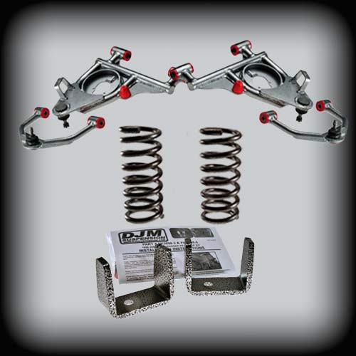
Upper and lower control arms combined with coil springs to lower the front 4 inches. The rear is dropped 5 inches using flip kit brackets.
Shocks are included with this kit. DJM Recommends:
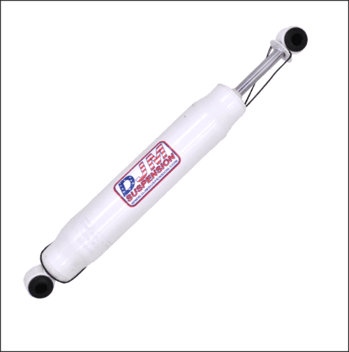
- Front Shock 1315 (sold each)
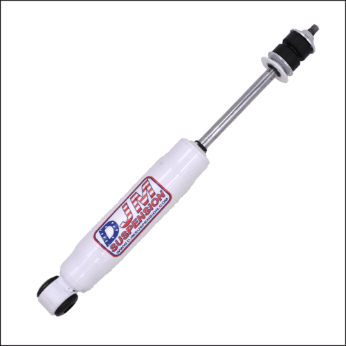
- Rear Drivers Shock 1800 (sold each)
- Rear Passenger's Shock 1900 (sold each)
Note: Shock mounts are staggered in the rear and need slightly different shock lengths.
Replacement Parts
Frequently Asked Questions
Additional information
1998–2014 Ford Ranger 4 inch Front Lowering Control Arms
| Weight | 30 lbs |
|---|
1998–2014 Ford Ranger Front Upper Control Arms
| Weight | 20 lbs |
|---|
1998–2014 Ford Ranger 2 inch Front Lowering Coil Springs
| Weight | 20 lbs |
|---|
1998-2010 Ford Ranger 5inch Rear Lowering Kit
| Weight | 10 lbs |
|---|
13.5″ Stem / Loop SuperShock (1315)
| Weight | 3 lbs |
|---|
18.5″ Loop / Loop SuperShock (1800)
| Weight | 3 lbs |
|---|
19.5″ Loop / Loop SuperShock (1900)
| Weight | 3 lbs |
|---|
Part # CA3098L-4, CA3098U, CS3098-2
1998–2007 Ford Ranger 4" Front Kit
Installation Instructions
Rev. # 7.04


Please take the time to read these installation instructions and check the Hardware Parts List to be sure you have all the listed parts.
DJM parts should be installed by qualified mechanics. If you are not familiar with automotive repair, have the parts installed by someone with experience.
Please read the warranty information (blue page enclosed). Complete your Product Warranty Card and mail it to DJM Suspension.
Please take a few minutes to fill out your installation helper (back side of warranty). Accurate measurements BEFORE BEGINNING INSTALLATION will show any irregularities in your vehicle.
NEVER WORK UNDER TRUCK SUPPORTED BY A JACK ONLY!!!
USE QUALITY JACK STANDS WHICH HAVE A RATING ADEQUATE FOR YOUR TRUCK'S WEIGHT!!!
THIS KIT IS DESIGNED TO BE USED WITH THE DJM COIL SPRINGS. USING ANOTHER BRAND OF COIL SPRINGS OR AIR BAGS WILL VOID DJM'S WARRANTY!!
INSTALLER MUST CHECK THAT THERE IS ABSOLUTELY NO CLEARANCE PROBLEMS BETWEEN THE WHEELS, THE SPINDLE, THE CALIPER, THE LOWER CONTROL ARMS AND ANY OTHER COMPONENT BEFORE DRIVING VEHICLE.
NEW FRONT SHOCKS #TS1315 ARE REQUIRED!
Hardware Parts List
| Part # | Contents |
|---|---|
| CA3098L-4 | 1 — Left Lower Control Arm w/ Ball Joint (8771T), bushings & sleeves 1 — Right Lower Control Arm w/ Ball Joint (8771T), bushings & sleeves 1 — Pair Sway Bar End Links 4 — 5/16" x 1" Bolts 4 — 5/16" Washers 6 — Grease Fittings |
| CA3098U | 1 — Left Upper Control Arm w/ Ball Joint (8738), bushings & sleeves 1 — Right Upper Control Arm w/ Ball Joint (8738), bushings & sleeves 6 — Grease Fittings |
| CS3098-2 | 1 — Pair Front Coil Springs 1 — Pair Flat Bump Stops |
Preparing the Twin Tube Pivot Sleeves
This kit uses DJM's twin tube pivot sleeves. YOU MUST ASSEMBLE THESE SLEEVES CORRECTLY. DO NOT SKIP THIS STEP!!
The outer sleeves are already installed in the control arms. You need to drill a small hole for the grease to pass through to the inner sleeve.
-
Using a 1/8" drill, line drill through the zerk fitting hole (Fig. 1). The drilling operation will leave a burr on the inside of the sleeve — this must be removed.

Fig. 1 — Line drill through the zerk fitting hole with a 1/8" drill -
Use a rat tail file to completely remove all burrs from drilling and on the ends of the sleeves (Fig. 2). Make sure you clean out any chips or dirt.
Fig. 2 — Remove all burrs from inside sleeve and ends with a rat tail file -
Install grease fittings (Fig. 3).
Fig. 3 — Install grease fitting into sleeve -
With the outer sleeves drilled and cleaned, check the inner sleeves. These sleeves should be about .050" longer than the outer sleeve. Assemble them before greasing to verify the length is slightly longer and they rotate smoothly. Apply some grease to the inner sleeve and insert into the control arm (Fig. 4).
Fig. 4 — Apply grease to inner sleeve and insert into control arm -
Install ball joint grease fitting (Fig. 5).
Fig. 5 — Install ball joint grease fitting


Preparing the Upper Arms
Now prepare the new DJM upper arms. Drill a hole through the grease fitting holes, through the bushing and sleeves. This hole will allow grease to pass through to the inside of the sleeve. Install grease fittings in the pivot tubes — the holes are pre-drilled. Using a nut driver is easiest. Carefully thread into the hole keeping them straight and tighten. Apply some grease to pivot sleeves and bushings. Clean factory pivot bolts and hardware.
Note: Rangers may not have adjusting cams on the upper control arm pivot bolt assembly. If cams are not installed, you will need to purchase and install them. Ask your Ford dealer or alignment shop for these parts. DJM uses Specialty Products #87500 (1995 & up, Ford Explorer).
Installation
-
Apply some grease to the upper pivot bolts and install the upper arm with factory hardware (Fig. 5). If your factory upper arms did not have alignment cams, installing them now will save you money.
Fig. 5 — Upper arm installed with factory hardware and alignment cams -
With the new DJM lower arm prepared, apply some grease to the lower pivot bolts. Hang the lower arm on the pivot bolts and hand tighten the nuts. Be sure the factory spring pad is attached to the top of the spring. Carefully rotate the control arm up making sure the spring is in the upper seat. As spring pressure comes into play, use your floor jack to raise the control arm the rest of the way until the spring is seated. Install the spindle to the lower ball joint and install the ball joint nut (Fig. 6).
Fig. 6 — Lower arm with coil spring seated in upper spring seat -
Install the upper ball joint in the spindle (Fig. 7). Tighten both ball joint nuts completely. Be sure they are tight and the taper is seated in the spindle.
Fig. 7 — Upper ball joint installed in spindle — tighten both ball joint nuts fully -
Install new sway bar links to the new control arms. You may need to raise the lower arms to align the end links. Grease all grease fittings. Install your new DJM front shocks (#TS1315) with the 5/16" x 1" bolts provided.
Install front shocks using the 5/16" x 1" bolts provided -
Inspect the installation to be sure all hardware is tight and all parts are clear and free to move without restrictions. Install front wheels and torque lug nuts. Check that the tires will turn both ways without hitting.
INSTALLER MUST CHECK THAT THERE IS ABSOLUTELY NO CLEARANCE PROBLEMS BETWEEN THE WHEELS AND TIRES, THE SPINDLE, THE CALIPER AND THE CONTROL ARMS BEFORE DRIVING VEHICLE.
-
If necessary, adjust the turning radius by grinding the contact point of the spindle. Wheels should turn approximately 25° from center in each direction.
-
Set your toe in/out close for the test drive. Turn your steering wheel until it is straight. Loosen the nut on the tie rod end and turn it until the tires are in a straight line from front to rear. Close is all you need — your alignment shop will correct this. Tighten the nuts.
-
Take your truck for a test drive. Start off slowly and listen for any unusual noises. Measure the height of the front and record on the installation helper. Your measurements should be about 4" less than the before measurement.
-
TAKE YOUR TRUCK TO A QUALIFIED ALIGNMENT SHOP FOR A PROFESSIONAL ALIGNMENT. ALIGN TO FACTORY SPECS.
-
After about 100 miles, check all bolts for correct torque.


Rev. #3.03
PART # CA3098U
INSTALLATION INSTRUCTIONS
1998-2007 Ford Ranger Upper Control Arms

DJM CA3098U Upper Control Arms — 1998–2007 Ford Ranger
Please take the time to read these INSTALLATION INSTRUCTIONS and check the Hardware Parts List to be sure you have all the listed parts.
DJM parts should be installed by qualified mechanics. If you are not familiar with automotive repair have the parts installed by someone with experience.
Please read the warranty information (blue page enclosed). Complete your Product Warranty Card and mail it to DJM Suspension.
Please take a few minutes to fill out your installation helper (back side of warranty). Accurate measurements BEFORE BEGINNING INSTALLATION will show any irregularities in your vehicle.
NEVER WORK UNDER TRUCK SUPPORTED BY A JACK ONLY !!! USE QUALITY JACK STANDS WHICH HAVE A RATING ADEQUATE FOR YOUR TRUCKS WEIGHT!!!
THIS KIT IS DESIGNED TO BE USED WITH THE DJM LOWER CONTROL ARMS #CA3098L-4 AND DJM COIL SPRINGS #CS3098-2. USING ANOTHER BRAND COIL SPRINGS OR AIR BAGS WILL VOID DJM'S WARRANTY!!
INSTALLER MUST CHECK THAT THERE IS ABSOLUTELY NO CLEARANCE PROBLEMS BETWEEN THE WHEELS, THE SPINDLE, THE CALIPER, THE LOWER CONTROL ARMS AND ANY OTHER COMPONENT BEFORE DRIVING VEHICLE.
Hardware Parts List:
| 1 | Left Upper Control Arm w/ Ball joint (8738), bushings & sleeves |
| 1 | Right Upper Control Arm w/ Ball joint (8738), bushings & sleeves |
| 6 | Grease Fittings |
Ranger's may not have adjusting cams on the upper control arm pivot bolt assembly. If cams are not installed, you will need to purchase and install them. Ask your Ford dealer or alignment shop/supplier for these parts. DJM uses "Specialty Products #87500 (1995 & up, Ford Explorer)".

Installation Steps
-
Drill a 1/8" hole in each grease fitting hole, through the bushing and sleeve. Remove any burrs on the inner sleeve. This hole will allow grease to pass through the bushings onto the pivot bolts.
Fig #1 — Drill 1/8" hole through bushing and sleeve
Fig #2 — Remove burrs from inner sleeve -
Install grease fittings into pivot tubes — the holes are pre-drilled and threaded. Using a nut driver is the easiest. Carefully thread into hole keeping them straight and tighten. Apply grease to the bushing and sleeves in control arm. Install grease fitting into ball joint. Apply some grease to pivot sleeves and bushings.
Fig #3 — Thread grease fitting into pivot tube
Fig #4 — Install grease fitting into ball joint -
Clean factory pivot bolts and hardware. Apply some grease to upper pivot bolts and install upper arm with factory hardware. If your factory upper arms did not have alignment cams, installing them now will save you some money.
Figure 5 — Install upper arm with factory hardware -
Next install upper ball joint in spindle. Now tighten both ball joint nuts completely. Be sure they are tight and the taper is seated in spindle.
Figure 6 — Install upper ball joint in spindle -
Now inspect the installation to be sure all hardware is tight, and all parts are clear and free to move without restrictions. Install front wheels and torque lug nuts. Check the tires will turn both ways without hitting.
INSTALLER MUST CHECK THAT THERE IS ABSOLUTELY NO CLEARANCE PROBLEMS BETWEEN THE WHEELS AND TIRES, THE SPINDLE, THE CALIPER AND THE CONTROL ARMS BEFORE DRIVING VEHICLE.
-
TAKE YOUR TRUCK TO A QUALIFIED ALIGNMENT SHOP FOR A PROFESSIONAL ALIGNMENT. ALIGN TO FACTORY SPECS.
-
After about 100 miles, check all bolts for correct torque.


PART # FK3098-3 & FK3098-5
1998-2010 Ford Ranger Rear Flip Kit
Installation Instructions
NOTE: 2010-2012 Ranger with Disc Brakes uses Part FK3010

Please take the time to read these Installation Instructions and check the Hardware Parts List to be sure you have all the listed parts.
These installation instructions are prepared for the professional installer with the proper equipment, tools and experience in suspension systems and safety. This vehicle and its components are extremely heavy and can be dangerous without the proper equipment and experience.
Please read the warranty information (blue page enclosed). Complete your Product Warranty Card and mail it to DJM Suspension.
Please take a few minutes to fill out your installation helper (back side of warranty). Accurate measurements BEFORE BEGINNING INSTALLATION will show any irregularities in your vehicle.
NEVER WORK UNDER TRUCK SUPPORTED BY A JACK ONLY!!!
USE QUALITY JACK STANDS WHICH HAVE A RATING ADEQUATE FOR YOUR TRUCK'S WEIGHT!!!
New shocks are required.
FK3098-3: Use DJM #TS1900 Driver side & TS2100 Passenger side.
FK3098-5: Use DJM #TS1800 Driver side & TS1900 Passenger side.
Hardware Parts List
| Axle Flip Kit | |
| 2 | Axle Locators (FK3001-4) |
| 2 | Spring Plates (3098-SP) |
| 2 | Urethane Bump Stops (10S) |
| (FK3098-3 Only) | |
| 2 | Urethane Bump Stops (10R) |
| 2 | Rear Shackles (SH1011-2) |
Relocating (Flipping) Rear Axle
-
Reverse the leaf spring center bolt so the nut is on the bottom.
-
Place the new axle locator bracket on top of the spring, with the off-center hole toward the front of the vehicle. This will center the rear axle and pull the drive shaft back from the transmission slightly.
Axle locator bracket positioned on top of spring with off-center hole toward front of vehicle -
Lower rear axle so the new axle supports fit up inside the existing rear axle pad welded to the axle. Install factory U-bolts and spring plates (5 hole) on the bottom of the springs. Cross-torque U-bolts.
Install factory U-bolts and spring plates on the bottom of the springs — cross-torque U-bolts -
(FK3098-3 Only) Replace factory shackles with DJM shackles. Use the holes furthest from the bushing.
FK3098-3 Only: Replace factory shackles with DJM shackles using holes furthest from the bushing -
Remove factory bump stop and install new stop to frame in existing hole.
Bump Stop Installed