
1999-2006 (2007 Classic) Silverado/Sierra 3 inch Front Lowering Control Arms
$453.96
Give your Silverado or Sierra the clean, level stance you want while you keep factory ride comfort and alignment geometry dialed in.
Lower the front of your 1999-2006 (2007 Classic) Silverado or Sierra by 3 inches with control arms that work with stock coil springs.
With these 99 06 Silverado lowering control arms, you can maintain proper alignment and drivability while removing wheel gap and improving your truck’s stance. And you can do this in a single bolt-on upgrade.
- 3-inch front drop with coils
- Corrects alignment for street use
- Includes new ball joints and bushings
Description
Why Buy from DJM Suspension
Trusted Lowering Expertise
DJM has specialized in lowering trucks since the 1970s, so you get components, like these lowering control arms for Silverado and Sierra, that fit and drive effortlessly.
Precision Engineered
We design each kit for daily use, towing within reason, and highway stability, so your lowered truck stays practical and predictable on real roads.
Made in the USA Quality
Our team builds and assembles suspension parts in the USA with tight quality control, so your investment offers consistent performance and long service life.
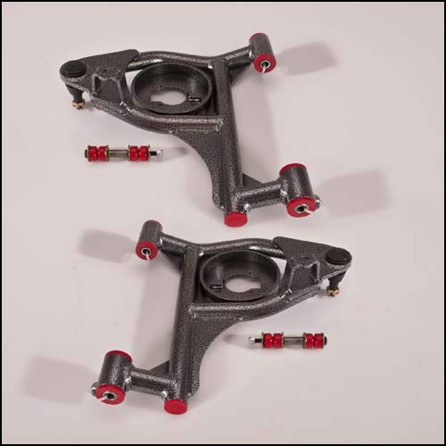
Control arms with stock coil springs drop the front 3 inches while keeping the factory alignment as well as avoiding any wheel and tire clearance issues. New ball joints, urethane bushings and "twin tube" pivot sleeves come assembled for simplified installation.
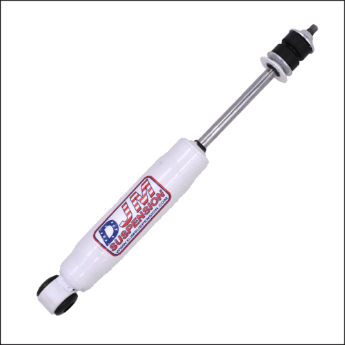
Shocks NOT included. DJM recommends:
- Front Shock 1415 (sold each)
- Replacement Ball Joint 6541 (Moog K6541)
- Replacement Bushing Kit BK2599L
Replacement Parts
About DJM Suspension
DJM Suspension grew from a family love for custom trucks and aftermarket performance. Since the early 1970s, we have focused on American-made lowering components that fit right and ride right. The team designs parts, like these Sierra and Silverado lowering control arms, to help you achieve the stance you want without sacrificing drivability or reliability.
Frequently Asked Questions
Additional information
| Weight | 45 lbs |
|---|
PART # CA2599L-2, CA2599L-3, CA2599L-4, CA2599L-5
1999-2006 Chevy C1500 Pickup Lower Control Arms
Installation Instructions
Rev. # 05-02

Please take the time to read these Installation Instructions and check the Hardware Parts List to be sure you have all the listed parts.
DJM parts should be installed by qualified mechanics. If you are not familiar with automotive repair have the parts installed by someone with experience.
Please read the warranty information (blue page enclosed). Complete your Product Warranty Card and mail it to DJM Suspension.
Please take a few minutes to fill out your installation helper (back side of warranty). Accurate measurements BEFORE BEGINNING INSTALLATION will show any irregularities in your vehicle.
NEVER WORK UNDER TRUCK SUPPORTED BY A JACK ONLY!!!
USE QUALITY JACK STANDS WHICH HAVE A RATING ADEQUATE FOR YOUR TRUCK'S WEIGHT!!!
This kit is designed to be used with the factory coil springs. Using aftermarket coil springs or air bags will void DJM's warranty!!
CA2599L-5 requires upper control arm DJM #CA2599U sold separately.
CA2599L-5 WILL NOT WORK WITH FACTORY WHEELS AND TIRES!!
INSTALLER MUST CHECK THAT THERE IS ABSOLUTELY NO CLEARANCE PROBLEMS BETWEEN THE WHEELS, THE SPINDLE, THE CALIPER, THE LOWER CONTROL ARMS AND ANY OTHER COMPONENT BEFORE DRIVING VEHICLE.
Hardware Parts List
| 1 | Left Lower Control Arm |
| 1 | Right Lower Control Arm |
| 8 | Pivot Bushings (Installed) |
| 1 | Set Twin Tube Sleeves |
| 4 | 16mm Nylock Nuts |
| 6 | Grease Fittings |
| 2 | Ball Joints (Installed, 6541) |
| 2 | Sway Bar End Links |
| 1 | Tube Loctite |
Twin Tube Sleeve Assembly
This kit uses DJM's twin tube pivot sleeves. YOU MUST ASSEMBLE THESE SLEEVES CORRECTLY. DO NOT SKIP THIS STEP!!
-
The sleeves are already installed in the control arms. Cut the zip tie holding the nut and inner sleeve. Remove the inner sleeve and set both aside.
-
A small hole is drilled for grease to pass through to the inner sleeve. Although this is done at the factory, check that there is a 1/8" hole drilled through the zerk fitting hole into the bushing and outer sleeve.

Fig #1 — Verify 1/8" hole is drilled through zerk fitting hole into bushing and outer sleeve -
The drilling operation will leave a burr on the inside of the sleeve that must be removed. Use a rat tail file to completely remove all burrs from drilling and from the ends of the sleeves. Make sure you clean out any chips or dirt.
Fig #2 — Use a rat tail file to completely remove all burrs from drilling and sleeve ends -
Install grease fittings.
Fig #3 — Install grease fittings -
With the outer sleeves drilled and cleaned, check the inner sleeves. These sleeves should be about .050" longer than the outer sleeve. Assemble them before greasing to confirm length is slightly longer and they rotate smoothly. Apply some grease to the inner sleeve and insert into the control arm.
Fig #4 — Apply grease to inner sleeve and insert into control arm -
Install ball joint grease fitting.
Fig #5 — Install ball joint grease fitting


Installation
-
Do not impact the pivot bolts. Clean bolts before installing. Replace factory nuts with the nylock nuts provided with the kit. Tighten to 30 lbs.
-
Before installing sway bar end links, loosen the 4 10mm bolts that hold the D-bushings to the frame. Install sway bar end links — you may need to raise the arm with a floor jack a little. DO NOT OVER TIGHTEN END LINKS!! 2 OR 3 THREADS PAST THE LOCK NUT IS ALL YOU NEED. Cycle the suspension to seat the sway bar and tighten D-bushings.
Correct — approximately 2-3 threads past the nylock nut
Incorrect — bolt is over-tightened -
Review all procedures and check that all parts are tight and installed correctly. Replace wheels and torque lug nuts. Check that the tires will turn both ways without making contact.
INSTALLER MUST CHECK THAT THERE IS ABSOLUTELY NO CLEARANCE PROBLEMS BETWEEN THE WHEELS AND TIRES, THE SPINDLE, THE CALIPER, THE CONTROL ARMS OR ANY OTHER COMPONENT BEFORE DRIVING VEHICLE.


Setting Toe and Alignment
To get the toe close, turn the tie rod ends in about 3 full turns. Turn your steering wheel until it is straight. By sighting down the tires and truck you can get the toe fairly close — adjustment is made with the tie rod ends. Loosen nuts at the rack and turn the tie rod ends until the tires are in a straight line from front to rear. Close is all you need; your alignment shop will correct this for you. Don't forget to tighten the nuts.
TAKE YOUR TRUCK TO A QUALIFIED ALIGNMENT SHOP FOR A PROFESSIONAL ALIGNMENT. ALIGN TO FACTORY SPECS.
Final Check
With the vehicle on the ground, measure the height of the front and record on your installation helper. Your measurements should be approximately 2-1/2" (CA25599L-2), 3-1/2" (CA2599L-4), and 4-1/2" (CA2599L-5) less than the before measurement.
REMEMBER: AFTER TEST DRIVING, INSPECT INSTALLATION AND DOUBLE CHECK ALL HARDWARE IS TIGHT.