1999 – 2006 Chevy Silverado/Sierra – 4 Inch Front 6 Inch Rear Lowering Kit (Shocks Included)
$1,051.59
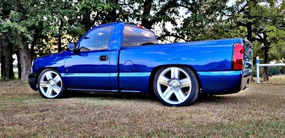
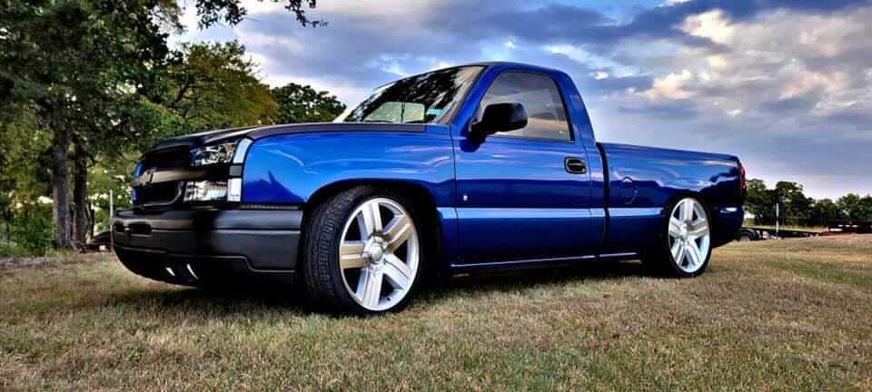
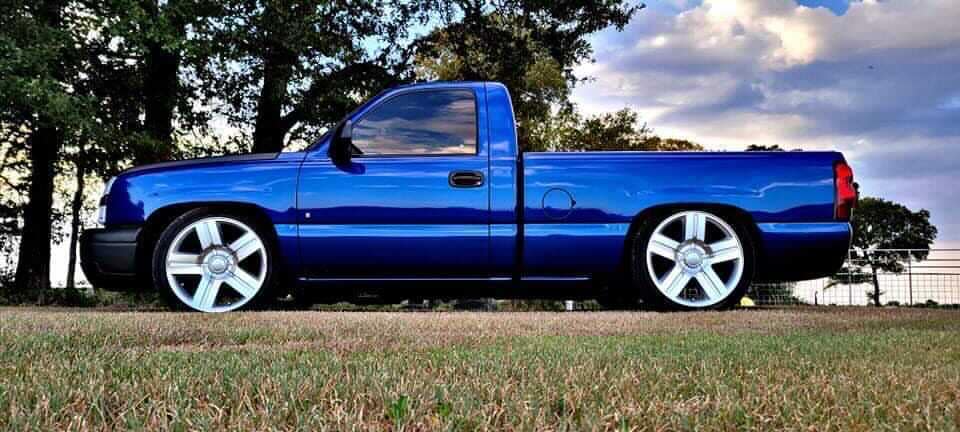
Give your truck the classic 4/6 stance with a Chevy Silverado/Sierra complete lowering kit from DJM Suspension. Designed for 1999-2006 models, this 4/6 drop kit combines matched front, rear, and shock components for a lower profile and controlled ride.
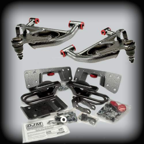
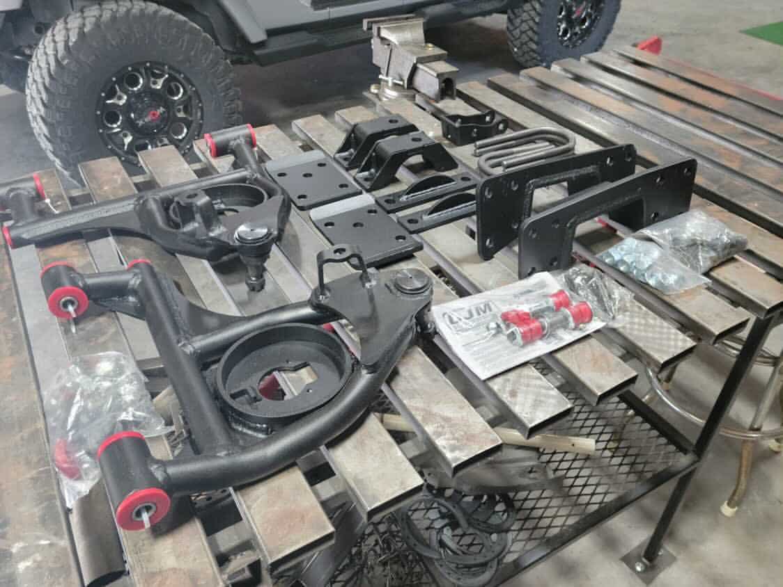
This 4/6 drop kit for 99-06 Silverado uses lowering control arms with the factory front springs for a 4-inch drop. The rear axle flip kit with frame supports brings the rear down 6 inches. Included SuperShocks complement the lowered suspension to help provide a controlled ride and aggressive street stance.
Description
Recommended Paired or Replacement Parts
DJM Recommends:
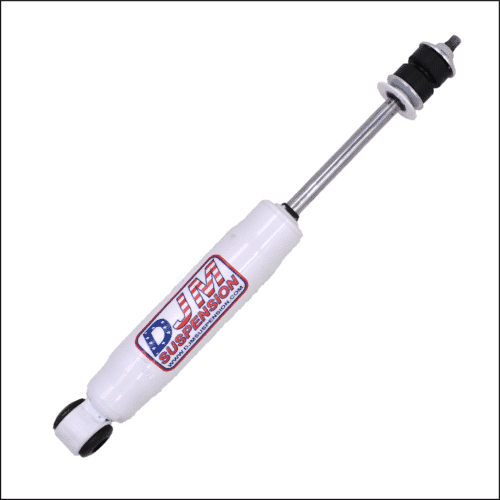
- Front Shock - 14.5″ Stem / Loop SuperShock (1415) (sold each)
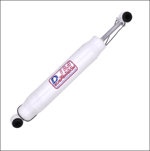
- Rear Drivers Shock - 18.5″ Loop / Loop SuperShock (1800) (sold each)
- Rear Passengers Shock - 19.5″ Loop / Loop SuperShock (1900) (sold each) (to be used with single side Shock extender included in the flip kit - 1999-2006 Chevy/GMC Silverado/Sierra Passengers Side Shock Extension Bracket)
Replacement Parts:
-
- Lower Ball Joint 6541
- Lower Bushing Kit BK2599L - 1999-2006 Chevy/GMC Silverado/Sierra Replacement Lower Bushing Kit
Why Buy from DJM Suspension
Get The Classic 4/6 Stance
Give your truck the unmistakable lowered profile that made the 4/6 setup a favorite among Chevy and GMC truck owners.
Get Matched Lowering Components
The 1999–2006 Chevy Silverado/Sierra lowering kit combines front control arms, a rear flip kit, frame supports, and application-specific shocks in one package.
Keep Your Truck Riding Smooth
A major drop should still feel good on the road. DJM Suspension pairs the lowering components with SuperShocks designed for lowered and performance trucks.
About DJM Suspension
DJM Suspension is a family-owned and operated American manufacturer with roots in the aftermarket automotive industry dating back to the early 1970s. From American-made lowering blocks to control arms and complete lowering systems, we have spent over five decades developing parts for truck and SUV owners who want a lower stance backed by proven suspension engineering.
Frequently Asked Questions
Give Your Silverado or Sierra the Classic 4/6 Drop
Build the lower stance you have in mind with a 4/6 Chevy Silverado/Sierra complete lowering kit from DJM Suspension, with matched components and SuperShocks included.
Additional information
1999-2006 (2007 Classic) Silverado/Sierra 4 inch Front Lowering Control Arms
| Weight | 45 lbs |
|---|
1999-2006 Chevy/GMC Silverado/Sierra 6inch Rear Lowering Kit
| Weight | 50 lbs |
|---|
14.5″ Stem / Loop SuperShock (1415)
| Weight | 3 lbs |
|---|
18.5″ Loop / Loop SuperShock (1800)
| Weight | 3 lbs |
|---|
19.5″ Loop / Loop SuperShock (1900)
| Weight | 3 lbs |
|---|
PART # CA2599L-2 & CA2599L-4, CA2599L-5
1999-2006 Chevy C1500 Pickup Lower Control Arms
Installation Instructions
Rev. # 05-02

Please take the time to read these installation instructions and check the Hardware Parts List to be sure you have all the listed parts.
DJM parts should be installed by qualified mechanics. If you are not familiar with automotive repair have the parts installed by someone with experience.
Please read the warranty information (blue page enclosed). Complete your Product Warranty Card and mail it to DJM Suspension.
Please take a few minutes to fill out your installation helper (back side of warranty). Accurate measurements BEFORE BEGINNING INSTALLATION will show any irregularities in your vehicle.
NEVER WORK UNDER TRUCK SUPPORTED BY A JACK ONLY !!!
USE QUALITY JACK STANDS WHICH HAVE A RATING ADEQUATE FOR YOUR TRUCK'S WEIGHT!!!
THIS KIT IS DESIGNED TO BE USED WITH THE FACTORY COIL SPRINGS. USING AFTER MARKET COIL SPRINGS OR AIR BAGS WILL VOID DJM'S WARRANTY!!
CA2599L-5 requires upper control arm DJM #CA2599U sold separately.
CA2599L-5 WILL NOT WORK WITH FACTORY WHEELS AND TIRES!!
INSTALLER MUST CHECK THAT THERE IS ABSOLUTELY NO CLEARANCE PROBLEMS BETWEEN THE WHEELS, THE SPINDLE, THE CALIPER, THE LOWER CONTROL ARMS AND ANY OTHER COMPONENT BEFORE DRIVING VEHICLE.
Hardware Parts List
| 1 | Left Lower Control Arm |
| 1 | Right Lower Control Arm |
| 8 | Pivot Bushings (Installed) |
| 1 | Set Twin Tube Sleeves |
| 4 | 16mm Nylock Nuts |
| 6 | Grease Fittings |
| 2 | Ball Joints (Installed, 6541) |
| 2 | Sway Bar End Links |
| 1 | Tube Loctite |
-
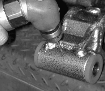
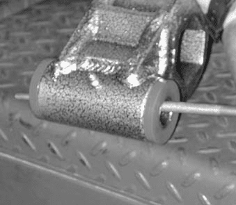
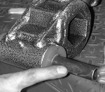
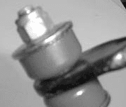
This kit uses DJM's twin tube pivot sleeves. YOU MUST ASSEMBLE THESE SLEEVES CORRECTLY. DO NOT SKIP THIS STEP!! The sleeves are already installed in the control arms. Cut the zip tie holding the nut and inner sleeve. Remove inner sleeve and set both aside. A small hole is drilled for the grease to pass though to the inner sleeve. Although this is done at the factory, check that there is a 1/8" hole drilled through the zerk fitting hole into the bushing and outer sleeve (Fig #1). The drilling operation will leave a burr on the inside of the sleeve and must be removed. Use a rat tail file to completely remove all burrs from drilling and on the ends of the sleeves (Fig #2). Make sure you clean out any chips or dirt. Install grease fittings (Fig #3). With the outer sleeves drilled and cleaned, it is important to check the inner sleeves. These sleeves should be about .050" longer than the outer sleeve. You should assemble them before greasing to check that length is slightly longer and they rotate smoothly. Now apply some grease to the inner sleeve and insert into control arm (Fig #4). Install ball joint grease fitting (Fig #5).

Fig #1
Fig #2
Fig #3
Fig #4
Fig #5 -
Do not impact the pivot bolts. Clean bolts before installing. Replace factory nuts with nylock nuts provided with kit. Tighten to 30 lbs.
-
Before installing sway bar end links, loosen the 4 10mm bolts that hold the D-bushings to the frame. Install sway bar end links. You may need to raise arm with floor jack a little. DO NOT OVER TIGHTEN END LINKS!! 2 OR 3 THREADS PAST THE LOCK NUT IS ALL YOU NEED. Cycle the suspension to seat sway bar and tighten D-bushings. Review all procedures and check that all parts are tight and installed correctly.
Correct: 2–3 threads past the nylock nut
Incorrect: over-tightened, too little thread showing -
Replace wheels and torque lug nuts. Check the tires will turn both ways without making contact. INSTALLER MUST CHECK THAT THERE IS ABSOLUTELY NO CLEARANCE PROBLEMS BETWEEN THE WHEELS AND TIRES, THE SPINDLE, THE CALIPER, THE CONTROL ARMS OR ANY OTHER COMPONENT BEFORE DRIVING VEHICLE.
-
To get the toe end close, turn the tie rod ends in about 3 full turns. Turn your steering wheel until it is straight. By sighting down the tires and truck you can get the toe fairly close. Adjustment is made with the tie rod ends. Loosen nuts at the rack and turn the tie rod ends until the tires are in a straight line from front to rear. Close is all you need, your alignment shop will correct this for you. Don't forget to tighten the nuts. TAKE YOUR TRUCK TO A QUALIFIED ALIGNMENT SHOP FOR A PROFESSIONAL ALIGNMENT. ALIGN TO FACTORY SPECS.
-
With the vehicle on ground measure height of front and record on installation helper. Your measurements should be about 2-1/2" (CA2599L-2), 3-1/2" (CA2599L-4) and 4-1/2" (CA2599L-5) less than the before measurement. REMEMBER AFTER TEST DRIVING INSPECT INSTALLATION AND DOUBLE CHECK ALL THE HARDWARE IS TIGHT.



PART #FK2599-6, FK2599-6X, FK2599-7 & FK2599-7X
1999-2005 Chevy 1500 Rear Flip Kit
Installation Instructions
Rev. # 10-02
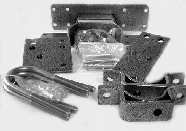
Please take the time to read these installation instructions and check the Hardware Parts List to be sure you have all the listed parts.
These installation instructions are prepared for the professional installer with the proper equipment, tools and experience in suspension systems and safety. This vehicle and its components are extremely heavy and can be dangerous without the proper equipment and experience.
Please read the warranty information (blue page enclosed). Complete your Product Warranty Card and mail it to DJM Suspension.
Please take a few minutes to fill out your installation helper (back side of warranty). Accurate measurements BEFORE BEGINNING INSTALLATION will show any irregularities in your vehicle.
NEVER WORK UNDER TRUCK SUPPORTED BY A JACK ONLY !!!
USE QUALITY JACK STANDS WHICH HAVE A RATING ADEQUATE FOR YOUR TRUCK'S WEIGHT!!!
New shocks are required.
Use DJM #1800 Driver side & 1900 Passenger side.
Hardware Parts List
Axle Flip Kit
| 2 | Universal Axle Locators (1010A) |
| 2 | Upper Axle Plates (1010P) |
| 4 | 5/8" U-Bolts (1025) |
| 8 | 5/8" x 18 Nylock Nuts |
| 8 | 5/8" Flat Washers |
| 2 | Leaf Spring Plates (1025) |
| 2 | Urethane Bump Stops (10S) |
| 2 | 5/8" x 11 x 3-1/2" Tap Bolts |
| 2 | 5/8" x 11 x 4" Tap Bolts |
| 8 | 5/8" Flat Washers |
| 4 | 5/8" x 11 Nylock Nuts |
Frame Support Kit
| 1 | Frame Support (Left) |
| 1 | Frame Support (Right) |
| 16 | 1/2" x 13 x 1.75" Bolts |
| 16 | 1/2" Flat Washers |
| 16 | 1/2" x 13 Nuts |
Shock Extender Kit
| 1 | Shock Extender (2599) |
| 2 | 1/2" x 20 x 1" Bolts |
| 2 | 1/2" x 20 Nuts |
| 2 | 1/2" x 13 x 2-3/4" Bolts |
| 1 | 1/2" x 13 Nuts |
| 1 | 3/8" x 16 x 1" Bolts |
| 1 | 3/8" x 16 Nuts |
FK2599-7 only:
| 2 | Rear 1012 Shackles |
Included with FK2599-6X & FK2599-7X:
| 1 | CB99 Carrier Bearing Bracket Kit |
Relocating (Flipping) Rear Axle
-
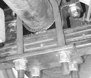
Reinstall the leaf spring under the axle. Place the new axle locator bracket on top of the spring, with the off center hole toward front of vehicle. This will center the rear axle and pull the drive shaft back from the transmission slightly. Lower the rear axle into the new axle supports. Rotate axle to desired pinion angle.
Axle relocated onto new axle locator -
Install new U-bolts and spring plates (5 hole) on the bottom of the springs. Cross-torque u-bolts. Over tightening may bend spring plates. Place the new upper axle plates, with the pin down, on top of the axle. Install and tighten the 5/8" bolts provided with one flat washer on top of the upper plate and one on the bottom of the axle locator.
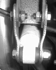
For FK2599-7 & FK2599-7X, replace factory shackles with DJM shackles.
For FK2599-7 & FK2599-7X, replace factory shackles with DJM shackles
For FK2599-7 & FK2599-7X, replace factory shackles with DJM shackles -
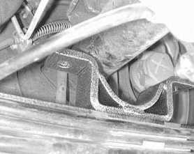
Installing Frame Supports. Frame supports are installed after axle is relocated. Raise the axle, and mark the center on the frame. Use this mark to center the frame support. Make a template or use one of the brackets and mark the frame. Use a sawzall, cutting wheel or plasma cutter to notch frame. Do not use a torch!! Move any wires or brake lines out of the way before cutting. Drill and bolt frame support to frame. Install bump stop on the frame support.
Frame support installed -
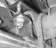
Before installing rear shocks, install the shock extender to the right side axle mount. This will make the shock work at a much better angle. Slide bracket over the factory mount and install the two 1/2" x 1" bolts from the outside and tighten. Line drill a 3/8" hole through the factory mount using the shock extender as a guide and install on 3/8" x 1" bolt and tighten. Now install the DJM #TS1800C driver side rear shock and the DJM #TS1900C on the passenger side.
Shock extender bracket installed -
Install rear wheels and torque lug nuts. Remove jack stand and floor jack. Test drive and adjust pinion angle as necessary. Measure and record the height of the rear on the installation helper.
-
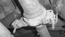
If drive line vibration occurs, with 2 piece drive shafts, install the Carrier Bearing Bracket #CB99 (included with FK2599-6X and FK2599-7X) to correct drive line angle.
Remove factory bracket from cross member
Position new bracket and drill two holes to attach bracket