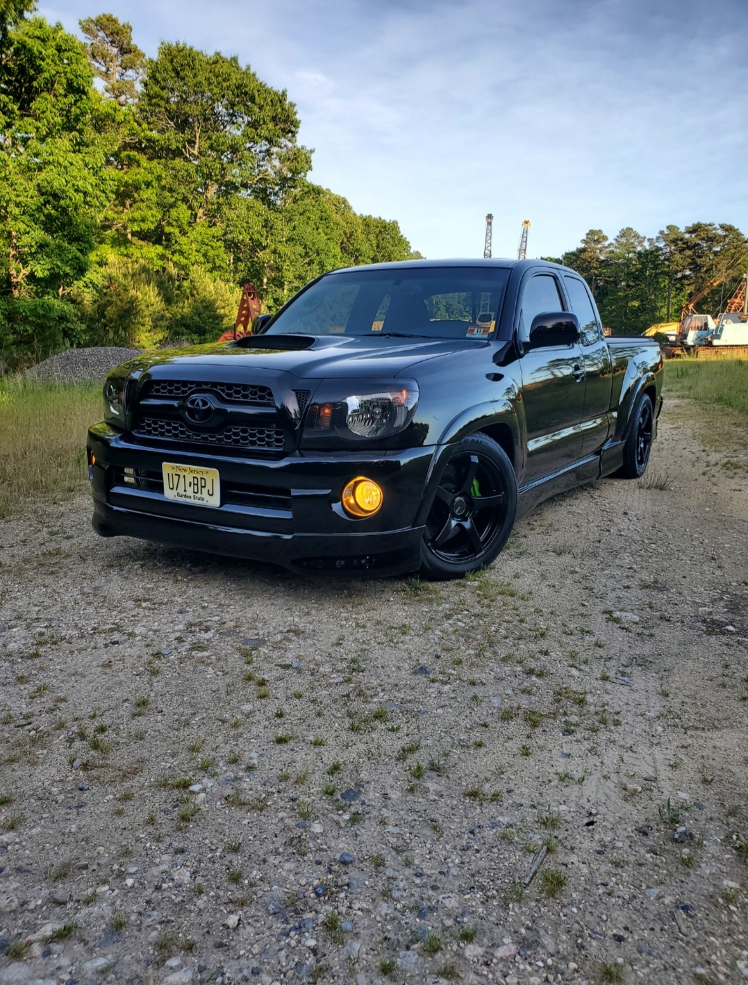
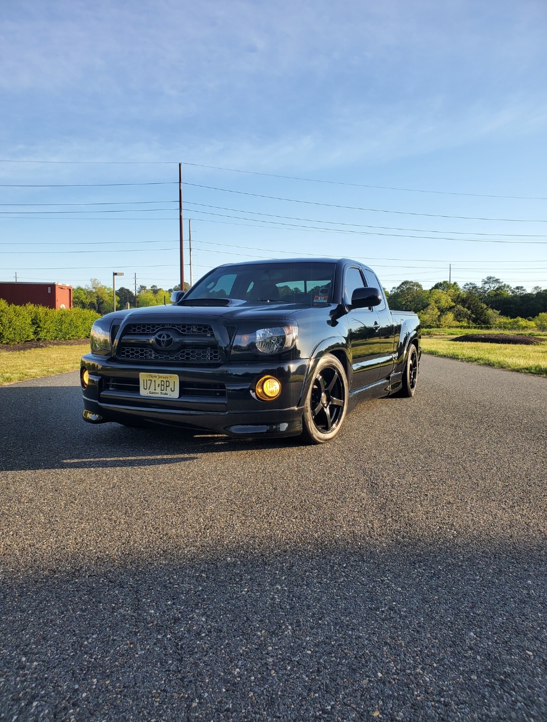
Tacoma 2005-2014 3 Inch” Complete Lowering Kit Shocks
$977.01
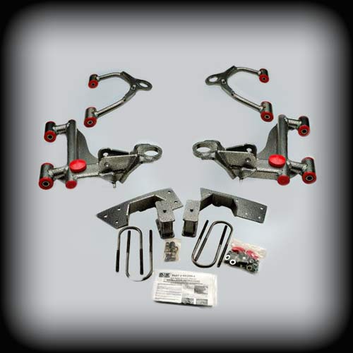
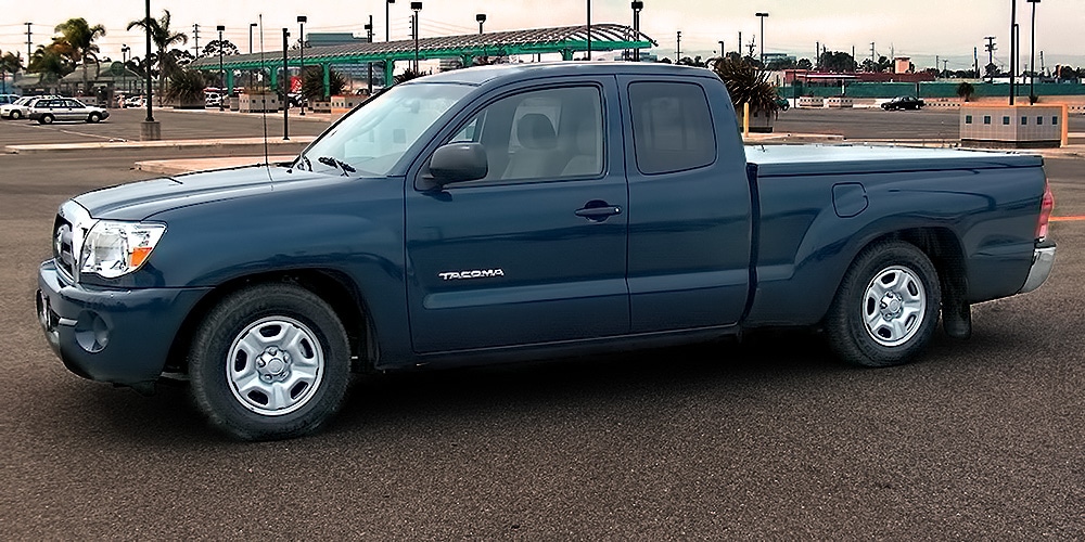
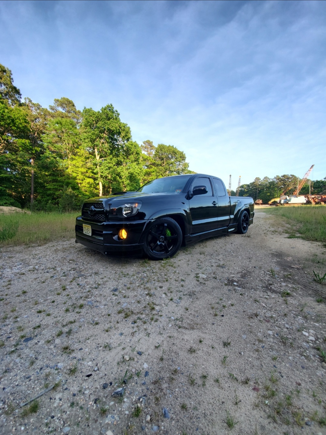
Give your 2005-2014 Toyota Tacoma a clean, aggressive look with a complete 3-inch front and 3-inch rear lowering kit. Designed for a great fit, smooth ride quality, and reliable handling, this Toyota Tacoma lowering kit includes everything you need for a professional installation.
Want your lowered 3rd gen Tacoma to look and work flawlessly? Use this complete suspension kit from DJM Suspension designed for a clean 3-inch front and rear drop.
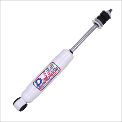
The front uses factory struts and coils with new upper and lower control arms to maintain full alignment and deliver a smooth, comfortable ride. The rear includes 3-inch all-steel lowering blocks, frame supports for the required C notch, and rear shocks for a complete installation.
- Retains factory struts and coils
- Full alignment capability
- Rear shocks included
Note: This kit is not compatible with Toyota Tacoma Pre-Runner models.
Description
Recommended Paired & Replacement Parts
Rear shocks are included with this kit. DJM recommends:
- Shock - 19.5″ Stem / Loop SuperShock (1910) (sold each)
Replacement Parts:
Why Buy from DJM Suspension
American Made Quality
DJM Suspension has built lowering kits in the USA for decades using components designed for dependable performance and long service life.
Complete Suspension Solution
This Toyota Tacoma lowering kit includes the major components needed for your lowering project, helping simplify installation by providing the major suspension components in one kit.
Trusted Since the 1970s
Thousands of truck owners have relied on DJM Suspension for proven lowering solutions backed by decades of industry knowledge.
About DJM Suspension
DJM Suspension is a family-owned American manufacturer with roots dating back to the early 1970s. Built by enthusiasts for enthusiasts, we focus on suspension products that deliver the right stance, dependable ride quality, and lasting value for truck owners across the country. When you choose DJM, you're choosing decades of experience backed by decades of suspension expertise.
Frequently Asked Questions
Upgrade Your Tacoma with Confidence
Get the aggressive stance and dependable performance your Tacoma deserves with a complete lowering kit from a trusted American manufacturer. Order the Toyota Tacoma 2005 2014 3-inch complete lowering kit with shocks now.
Instructions
Additional information
2005–2014 Toyota Tacoma Complete 3 inch Front Lowering Kit
| Weight | 45 lbs |
|---|
2005-2014 Toyota Tacoma Complete 3 inch Rear Lowering Kit
| Weight | 30 lbs |
|---|
19.5″ Stem / Loop SuperShock (1910)
| Weight | 3 lbs |
|---|
PART # CA2806-3
2006 Toyota Tacoma 3” Front Upper and Lower Control Arms
Installation Instructions
Rev. # 9-06

Please Note: Unless specifically stated, all DJM lowering components are intended for two wheel drive applications only!!!
Please take the time to read these installation instructions and check the Hardware Parts List to be sure you have all the listed parts.
These installation instructions are prepared for the professional installer with the proper equipment, tools and experience in suspension systems and safety. This vehicle and its components are extremely heavy and can be dangerous without the proper equipment and experience.
Please read the warranty information (blue page enclosed). Complete your Product Warranty Card and mail it to DJM Suspension.
Please take a few minutes to fill out your installation helper (back side of warranty). Accurate measurements before beginning installation will show any irregularities in your vehicle.
NEVER WORK UNDER TRUCK SUPPORTED BY A JACK ONLY!!! USE QUALITY JACK STANDS WHICH HAVE A RATING ADEQUATE FOR YOUR TRUCK'S WEIGHT!!!
THIS KIT REQUIRES THE FACTORY UPPER AND LOWER BALL JOINTS TO BE PRESSED OUT OF FACTORY ARMS AND PRESSED INTO YOUR NEW DJM ARMS.
Designed for use with factory struts and springs only.
INSTALLER MUST CHECK THAT THERE IS ABSOLUTELY NO CLEARANCE PROBLEMS BETWEEN THE WHEELS, THE SPINDLE, THE CALIPER, THE LOWER CONTROL ARMS AND ANY OTHER COMPONENT BEFORE DRIVING VEHICLE.
Hardware Parts List
| 1 | Left lower arm |
| 1 | Right lower arm |
| 2 | Front bump stops |
| 1 | Left upper arm |
| 1 | Right upper arm |
Before beginning installation, measure and record the height of the truck on the installation helper.
Factory ball joints are used in new control arms. A hydraulic press is required to install this kit. Extra care must be used in removing and pressing ball joints into the new arms. Replacement ball joints are only available by purchasing them with new control arms.
DJM suggests removing the ball joint boots carefully and setting them aside when pressing ball joints, so they are not damaged.
- Working on one side at a time, remove the upper control arm first. Do not start on the lower arms until the new uppers are installed on the truck. The bracket for the ABS will be installed on the new arms with the bolts provided.
-
Remove clip holding the boot.
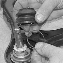
Fig #1 — Remove clip holding the boot -
The upper arm has the C-clip on the bottom of the arm. Remove the C-clip and press out the ball joint.
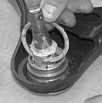
Fig #2 — Remove C-clip and press out ball joint -
Install in new arms and reinstall the C-clip and the boot.
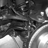
Fig #3 — Install in new arms and reinstall the C-clip and boot -
Install grease fitting in the new arm, and apply plenty of grease to the bushings. Install new upper arms using factory hardware. Attach ABS bracket and tighten.
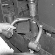
Fig #4 — Install new upper arms using factory hardware; attach ABS bracket and tighten - With the upper arm installed, remove the bolt holding the strut to the lower control arm. Next unbolt the ball joint, sway bar end links, and finally the pivot bolts. Keep all hardware.
-
Remove clip holding the boot. Next remove C-clip from top of lower ball joint.
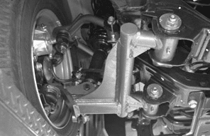
Fig #5 — Remove clip holding the boot, then remove C-clip from top of lower ball joint -
Using a hydraulic press, press out the factory ball joint and carefully install into the new arms. Reinstall boot and C-clip.
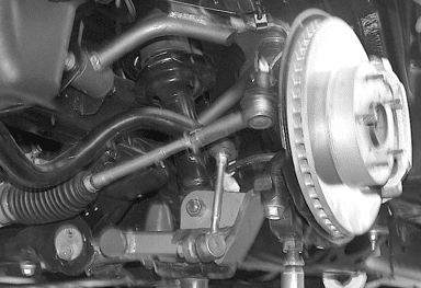
Fig #6 — Press out factory ball joint and install into new arms -
This lower arm uses DJM's twin tube pivot sleeves. You must assemble these sleeves correctly. Do not skip this step!! Cut the zip tie, remove the inner sleeve and set them aside. The outer sleeves are already installed in the control arms. An 1/8" hole is needed for the grease to pass through to the inner sleeve. This hole is drilled from the factory, check that the hole is through both the bushing and the sleeve.
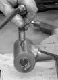
Fig #7 — Cut the zip tie and remove the inner sleeve; check the 1/8" grease hole -
The drilling operation will leave a burr on the inside of the sleeve and it must be removed. Use a rat tail file to completely remove all burrs from drilling and on the ends of the sleeves. Make sure to clean out any chips or dirt.
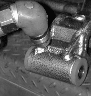
Fig #8 — Use a rat tail file to remove all burrs from drilling -
Install grease fittings.
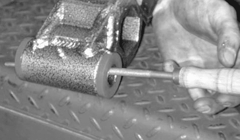
Fig #9 — Install grease fittings - With the outer sleeves drilled and cleaned it is important to check the inner sleeves. These sleeves should be about .050" longer than the outer sleeve. Assemble them before greasing to check that the length is slightly longer and they rotate smoothly. Check the width of the mounting brackets — test fit the arm, the bushing should slip into the mount fairly easily. If they are real tight, separate the mounts a bit.
-
Now apply some grease to the inner sleeve and insert into the control arm.
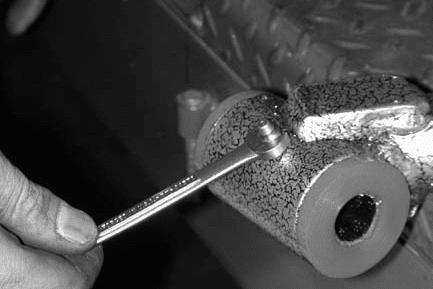
Fig #10 — Apply grease to the inner sleeve and insert into control arm -
Pre-grease fittings with a grease gun to test it will flow properly and apply some grease to the bushing.
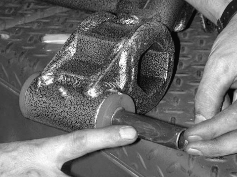
Fig #11 — Pre-grease fittings with a grease gun and apply grease to the bushing -
Install new lower arm using factory hardware.
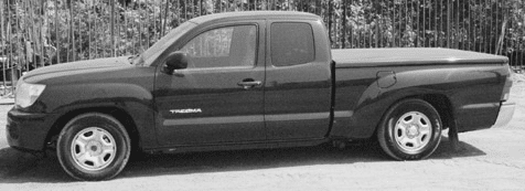
Fig #12 — Install new lower arm using factory hardware 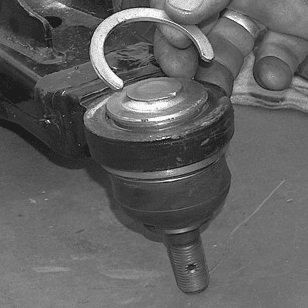
Fig #13 — Install new lower arm using factory hardware


Check all hardware has been tightened. When installation is complete, test drive vehicle. A front end alignment is required. Align to factory specifications.
Measure and record the completed height of truck on installation helper. Double check all bolts. It is recommended to check all bolts after about one hundred miles.
PART # RK2806-3
2006 Toyota Tacoma 3” Rear Kit
Installation Instructions
Rev. # 6-06
Please Note: Unless specifically stated, all DJM lowering components are intended for two wheel drive applications only!!!
Please take the time to read these installation instructions and check the Hardware Parts List to be sure you have all the listed parts.
These installation instructions are prepared for the professional installer with the proper equipment, tools and experience in suspension systems and safety. This vehicle and its components are extremely heavy and can be dangerous without the proper equipment and experience.
Please read the warranty information (blue page enclosed). Complete your Product Warranty Card and mail it to DJM Suspension.
Please take a few minutes to fill out your installation helper (back side of warranty). Accurate measurements before beginning installation will show any irregularities in your vehicle.
NEVER WORK UNDER TRUCK SUPPORTED BY A JACK ONLY!!! USE QUALITY JACK STANDS WHICH HAVE A RATING ADEQUATE FOR YOUR TRUCK'S WEIGHT!!!
THIS KIT REQUIRES NOTCHING THE FRAME AND INSTALLING FRAME SUPPORT BRACKETS FOR SUFFICIENT AXLE CLEARANCE.
Hardware Parts List
| 1 | Left frame support |
| 1 | Right frame support |
| 2 | Rear bump stops |
| 14 | 7/16" x 14 x 1-1/4 bolts |
| 14 | 7/16" x 14 nylock nuts |
| 28 | 7/16" flat washers |
| 2 | 3" steel lowering blocks |
| 2 | 2 degree pinion shims |
| 4 | 1/2" x 10-1/2" u-bolts |
| 8 | 1/2" nuts |
| 8 | 1/2" lock washers |
| 2 | 5/8" ring shims |
Before beginning installation, measure and record the height of the truck on the installation helper.
-
The rear lowering blocks are installed between the axle and the leaf spring. Place the 5/8" ring shim on the leaf spring center pin.

Fig #1 — Place the 5/8" ring shim on leaf spring center pin -
Install block with pinion shim on top, with the thick end to the rear. The thin end of the block is installed to the front of the truck. Be sure the hole on the bottom of the block is aligned with the leaf spring center pin and the pin on the top of the block is aligned with the hole in the axle. Secure in place with new u-bolts. Trim excess u-bolt if needed.
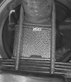
Fig #2 — Install block with pinion shim on top, thick end to the rear; secure with new u-bolts -
A frame notch is required to allow enough clearance for the axle. Remove the factory bump stop bracket.
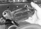
Fig #3 — Remove the factory bump stop bracket for axle clearance -
Using the template supplied, align the two existing holes in the frame above the axle. Mark and cut the notch. Smooth out cuts with a grinder and spray paint raw edges. Bolt the notch with two 7/16" bolts to the existing holes in the frame. Mark and drill remaining 1/2" holes.
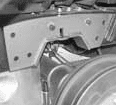
Fig #4 — Align the template, mark and cut the notch 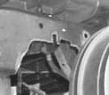
Fig #5 — Bolt the notch with two 7/16" bolts to the existing holes in the frame - Install remaining 7/16" bolts and tighten.
-
Attach the new bump stop to the notch.
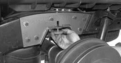
Attach the new bump stop to the notch


Check all hardware has been tightened. When installation is complete, test drive vehicle.
Measure and record the completed height of truck on installation helper. Double check all bolts. It is recommended to check all bolts after about one hundred miles.