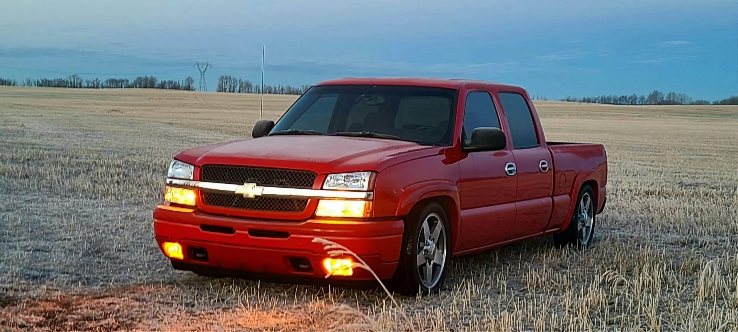


2001-2010 Chevy Silverado/Sierra 1500HD, 2500HD, 3500HD 6″ Front / 8″ Rear Complete Lowering Kit (Shocks Included)
$2,340.97
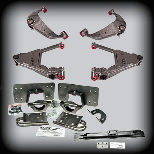
Need a lowering kit for your Chevy Silverado 1500? Give your Silverado or Sierra HD a lower stance with a complete suspension kit designed for a balanced ride and dependable performance. This DJM lowering kit includes the components you need for a clean installation without mixing and matching parts.
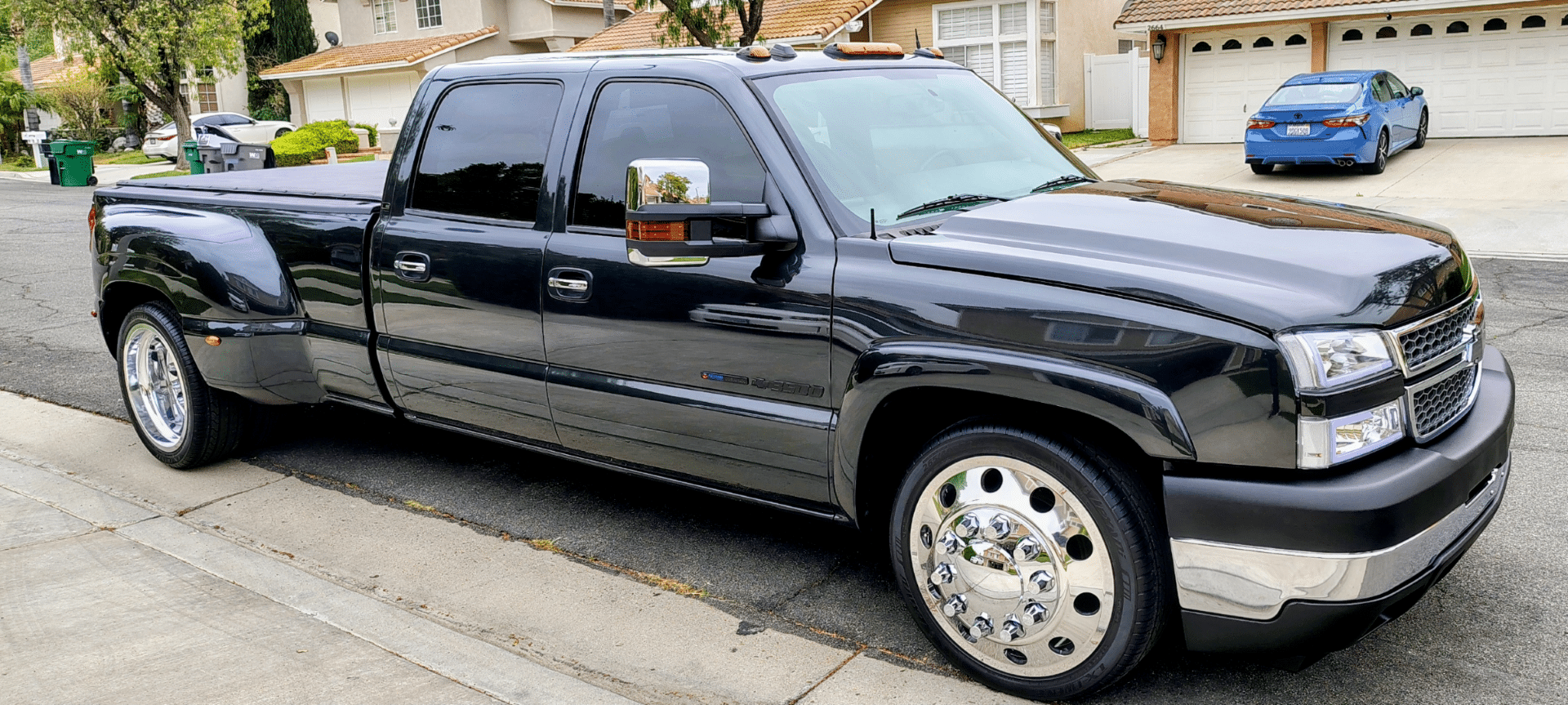
Lower your 2001-2010 Chevy Silverado or GMC Sierra 1500HD, 2500HD, or 3500HD with this complete 6-inch front and 8-inch rear DJM lowering kit.
The front setup uses heavy-duty upper and lower control arms with the factory torsion bars to maintain proper alignment, ball joint angles, ground clearance, and ride quality.
The rear axle flip kit includes reinforced frame supports with a C-notch, adjustable axle brackets for pinion angle correction, and a relocated crossmember that raises the transmission for added ground clearance.
This 2001 Silverado lowering kit creates a lower stance with balanced suspension geometry and dependable performance.
- 6″ front, 8″ rear drop
- Twin-tube pivot sleeves for secure, bushing-friendly installation.
- Shocks included, ready to install
- Bushings and ball joints pre-installed
- Description
- Additional information
- Control Arms Instructions
- Upper Control Arm Instructions
- Transmission Cross Member Instructions
- Rear Flip Kit Instructions
Description
Recommended Paired or Replacement Parts
We recommend using these replacement parts to service or upgrade your suspension.
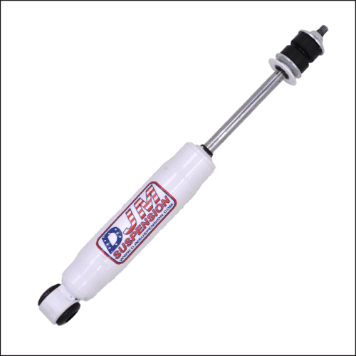
- Front Shock - 14.5″ Stem / Loop SuperShock (1415) (sold each)
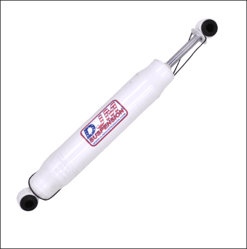
- Rear Drivers Shock - 17.5″ Loop / Loop SuperShock (1700) (sold each)
- Rear Passengers Shock - 18.5″ Loop / Loop SuperShock (1800) (sold each)
- Upper Ball Joint
- Lower Ball Joint 6541
- Upper Bushing Kit - Replacement Bushing kit for Calmax Upper Control arms
- Lower Bushing Kit - BK2699L
Why Buy from DJM Suspension
Complete Kit Convenience
Everything is designed to work together, helping you avoid the guesswork of sourcing individual suspension components.
Reliable Performance
Each DJM lowering kit is engineered for proper fitment, dependable durability, and a confident driving experience on the street.
Built to Last
DJM control arms feature twin-tube pivot sleeves that provide a secure, bushing-friendly fit built to last mile after mile.
About DJM Suspension
DJM Suspension was born out of a love for all things aftermarket automotive. As a family-owned and operated American-made manufacturer, we've led the lowering industry since the early 1970s, bringing decades of hands-on experience to every lowering kit we build.
Frequently Asked Questions
Ready to Lower Your HD Truck?
Upgrade your Chevy Silverado or GMC Sierra HD with a complete DJM lowering kit designed for proven fitment, quality components, and an aggressive lowered stance.
Instructions
Additional information
2001-2010 1500/2500/3500 HD 6 inch Lowering Control Arm (Drivers Side Only)
| Weight | 20 lbs |
|---|
2001-2010 1500/2500/3500 HD 6 inch Lowering Control Arm (Passenger Side Only)
| Weight | 20 lbs |
|---|
2001-2010 1500/2500/3500 HD Upper Control Arms (2WD only)
| Weight | 20 lbs |
|---|
2001–2010 1500/2500/3500 HD 8 inch Lowering Rear Axle Flip Kit
| Weight | 50 lbs |
|---|
2001 – 2010 Chevy HD Transmission cross member
| Weight | 20 lbs |
|---|
14.5″ Stem / Loop SuperShock (1415)
| Weight | 3 lbs |
|---|
18.5″ Loop / Loop SuperShock (1800)
| Weight | 3 lbs |
|---|
17.5″ Loop / Loop SuperShock (1700)
| Weight | 3 lbs |
|---|
PART # CA2699L-6D & CA2699L-6P
2001-2006 Chevy HD Lower Control Arms
Installation Instructions
Rev. # 07-04

Please Note: Unless specifically stated, all DJM lowering components are intended exclusively for two wheel drive applications only!!!
Please take the time to read these installation instructions and check the Hardware Parts List to be sure you have all the listed parts.
These installation instructions are prepared for the professional installer with the proper equipment, tools and experience in suspension systems and safety. This vehicle and its components are extremely heavy and can be dangerous without the proper equipment and experience.
Please read the warranty information (blue page enclosed). Complete your Product Warranty Card and mail it to DJM Suspension.
Please take a few minutes to fill out your installation helper (back side of warranty). Accurate measurements before beginning installation will show any irregularities in your vehicle.
NEVER WORK UNDER TRUCK SUPPORTED BY A JACK ONLY!!! USE QUALITY JACK STANDS WHICH HAVE A RATING ADEQUATE FOR YOUR TRUCK'S WEIGHT!!!
This kit is not designed for air bags. New front shocks DJM #TS1315 are required.
Hardware Parts List
| CA2699L-6D | |
| 1 | Left lower control arm |
| 1 | Ball joint (installed, 6541) |
| 4 | Pivot bushings (installed) |
| 2 | Inner sleeves (installed) |
| 2 | Outer sleeves (zip-tied to arm) |
| 2 | 16mm nylock nuts (zip-tied to arm) |
| 2 | Bump stops (10R) |
| 2 | 1/2" x 13 nuts (1 for each arm) |
| 2 | 1/2" x 13 x 2-3/4" shock bolts (1 for each arm) |
| 2 | Grease fitting & cotter pin bags (1 for each arm, for ball joints) |
| 4 | Grease fittings (2 for each arm, for pivot bushings) |
| CA2699L-6P | |
| 1 | Right lower control arm |
| 1 | Ball joint (installed, 6541) |
| 4 | Pivot bushings (installed) |
| 2 | Inner sleeves (installed) |
| 2 | Outer sleeves (zip-tied to arm) |
| 2 | 16mm nylock nuts (zip-tied to arm) |
Notice to end user: This kit is very low and could cause clearance problems depending on road, driveway or other conditions. The frame on this kit with the stock tires measures 5.5" of ground clearance. You also may lose some weight capacity in the rear end due to the removal of the upper overload springs. We recommend that you read through the instructions, contact DJM's tech line and ask your installer about your needs and compatibility with this kit. If you decide not to install this kit, you may return it for a full refund within 30 days of the purchase date. Kits returned must be unused and in the original boxes to be given a refund.
The lower arms use DJM's twin tube pivot sleeves. You must assemble these sleeves correctly. Do not skip this step!!
- The sleeves are already installed in the control arms. Cut the zip tie holding the nut and inner sleeve. Remove the inner sleeve and set both aside. A small hole is drilled for the grease to pass though to the inner sleeve. Although this is done at the factory, check that there is a 1/8" hole drilled through the zerk fitting hole into the bushing and outer sleeve.

Fig #1 — Check that there's a 1/8" hole through the bushing and outer sleeve - The drilling operation will leave a burr on the inside of the sleeve and must be removed. Use a rat tail file to completely remove all burrs from drilling and on the ends of the sleeves. Make sure you clean out any chips or dirt.
Fig #2 — Use a rat tail file to remove all burrs from drilling - Install grease fittings.
Fig #3 — Install grease fittings - With the outer sleeves drilled and cleaned, it is important to check the inner sleeves. These sleeves should be about .050" longer than the outer sleeve. You should assemble them before greasing to check that length is slightly longer and they rotate smoothly. Now apply some grease to the inner sleeve and insert into the control arm.
Fig #4 — Apply grease to the inner sleeve and insert into control arm - Install ball joint grease fitting.
Fig #5 — Install ball joint grease fitting - Locate the torsion key. From the lower control arm follow the torsion bar to the rear of the truck. The key is in the cross member. With white paint or grease pencil, mark the bolt at the torsion key. This will help you when you reinstall the torsion bar. Remove the torsion key bolt.
Fig #6 — Locate the torsion key and mark the bolt before removal - Place a floor jack under the lower control arm and raise slightly. Remove the lower ball joint nut. Free the lower ball joint from the spindle. Remove the tie rod end from the spindle. Using the floor jack, slowly lower the control arm until the tension is removed from the torsion bar.
Fig #7 — Free the lower ball joint from the spindle - Remove the torsion key. Remove the pivot bolts from the control arm, and remove the arm and the torsion bar.
Fig #8 — Remove the torsion key, pivot bolts, and the arm and torsion bar - Cleaning the end of the torsion bar and removing the powder coating will make the torsion bar fit much easier into the new arms. Apply grease to the bushing and sleeves in the control arm. Slide the torsion bar through the control arm.
Fig #9 — Apply grease and slide torsion bar through control arm - Install the pivot bolts though the frame mounts and control arm bushings. Use the new nylock nuts included with kit.
Fig #10 — Install pivot bolts through frame mounts and control arm bushings
Fig #11 — Use the new nylock nuts included with kit - Raise the control arm to ride height (flat with the ground). Slide the torsion key up into the cross member and move the torsion bar back to align with the key. Install the torsion adjustment bolt, do not tighten yet.
- Raise the control arm enough to install the lower ball joint. Install the nut, tighten, and install new cotter pins.
- Install sway bar end links but do not tighten. You may need to raise the arm a little to align bolts.
- Factory bump stops must be replaced. Remove the factory bump stop and install the new red bump stop.
Fig #12 — Remove factory bump stop and install new red bump stop - Install new shocks with 1/2" x 2-3/4" bolts supplied. Review installation and check that all bolts are tight and installed correctly. Now you can tighten the torsion adjustment bolt to the marks made earlier.
- Replace wheels and torque lug nuts. Check the tires will turn both ways without making contact. Installer must check that there is absolutely no clearance problems between the wheels and tires, the spindle, the caliper, the control arms or any other component before driving vehicle.
- Review all procedures and check that all parts are tight and installed correctly. The completed installation will measure 18" from the center of the front wheel to the fender well. Excessive lowering may cause damage to the control arms and void warranty.
- To get the toe close, turn the tie rod end in about 3 full turns. Turn your steering wheel until it is straight. By sighting down the tires and truck you can get the toe fairly close. Adjustment is made with the tie rod ends. Loosen the nuts at the rack and turn the tie rod ends until the tires are in a straight line from front to rear. Close is all you need, your alignment shop will correct this for you. Don't forget to tighten the nuts.


Take your truck to a qualified alignment shop for a professional alignment. Align to factory specs.
PART # CA2699U
2001-2010 Chevy HD Upper Control Arms
Installation Instructions

Please take the time to read these installation instructions and check the Hardware Parts List to be sure you have all the listed parts.
These installation instructions are prepared for the professional installer with the proper equipment, tools and experience in suspension systems and safety. This vehicle and its components are extremely heavy and can be dangerous without the proper equipment and experience.
Hardware Parts List
| 2 | Upper control arms |
| 2 | Ball joints (6292) |
| 8 | Pivot bushings with twin tube sleeves (installed) |
| 4 | Grease fittings |
| 4 | Zip ties |
Both control arms are the same and can be installed on either side.
- Install the grease fitting on the twin tube sleeves. Make sure to pre-grease the sleeves to make sure the predrilled holes are free and the grease flows smoothly. If the ball joint is greasable then grease it at this time. If it is maintenance free (no grease fitting) no action is necessary.
Install the grease fitting on the twin tube sleeves; pre-grease so the predrilled holes flow smoothly - There are 2 small holes in the plate behind the ball joint. They are for the factory plastic rivet used to hold the ABS sensor.
2 small holes behind the ball joint hold the factory ABS sensor rivet - The 4 larger holes are for the brake lines. Use the zip ties supplied to secure.
Use the zip ties supplied to secure the brake lines through the 4 larger holes - Grease the twin sleeves and bolt the ball joint as shown, torqued to 60 ft-lbs. Zip ties are provided to secure the brake line.
Grease twin sleeves; bolt ball joint as shown (60 ft-lbs); zip ties secure the brakeline - Now install and align the arms to factory specifications.


PART # CM2699
2001 Chevy HD Cross Member
Installation Instructions
Rev. # 10-01

Please take the time to read these installation instructions and check the Hardware Parts List to be sure you have all the listed parts.
These installation instructions are prepared for the professional installer with the proper equipment, tools and experience in suspension systems and safety. This vehicle and its components are extremely heavy and can be dangerous without the proper equipment and experience.
Crossmember designed for automatic transmission.
Hardware Parts List
| 1 | Cross member |
| 1 | Trans bracket |
This part is used for ground clearance. Remove the factory cross member and replace using all the original hardware.
Use trans bracket if needed.


PART # FK2699-8
2001-2010 Chevy 1500/3500 HD Rear Flip Kit
Installation Instructions
Rev. # 10-02

Please take the time to read these installation instructions and check the Hardware Parts List to be sure you have all the listed parts.
These installation instructions are prepared for the professional installer with the proper equipment, tools and experience in suspension systems and safety. This vehicle and its components are extremely heavy and can be dangerous without the proper equipment and experience.
Please read the warranty information (blue page enclosed). Complete your Product Warranty Card and mail it to DJM Suspension.
Please take a few minutes to fill out your installation helper (back side of warranty). Accurate measurements before beginning installation will show any irregularities in your vehicle.
NEVER WORK UNDER TRUCK SUPPORTED BY A JACK ONLY!!! USE QUALITY JACK STANDS WHICH HAVE A RATING ADEQUATE FOR YOUR TRUCK'S WEIGHT!!!
New shocks are required. Use DJM #1500 driver side & 1800 passenger side.
Hardware Parts List
| Axle Flip Kit | |
| 2 | Universal axle locators (1010A) |
| 2 | Upper axle plates (1010P) |
| 4 | 5/8" U-bolts (1026) |
| 8 | 5/8" x 18 nuts |
| 8 | 5/8" flat washers |
| 2 | Leaf spring plates (1026) |
| 2 | Urethane bump stops (10R) |
| 2 | 3/8" x 24 x 5" spring center pins |
| 2 | 3/8" x 24 nylock nuts |
| 2 | 5/8" x 11 x 4" tap bolts |
| 2 | 5/8" x 11 x 4-1/2" tap bolts |
| 8 | 5/8" flat washers |
| 4 | 5/8" x 11 nylock nuts |
| Frame Support Kit (2699) | |
| 1 | Frame support (left) |
| 1 | Frame support (right) |
| 16 | 1/2" x 13 x 1.75" bolts |
| 16 | 1/2" SAE flat washers |
| 16 | 1/2" x 13 nylock nuts |
| Carrier Bearing Bracket | |
| 1 | Bracket (CB99) |
| 2 | 3/8" x 16 nylock nuts |
| 2 | 3/8" x 16 x 3" bolts |
| 4 | 3/8" flat washers |
Notice to end user: This kit is very low and could cause clearance problems depending on road, driveway or other conditions. The frame on this kit with the stock tires measures 5.5" of ground clearance. You also may lose some weight capacity in the rear end due to the removal of the upper overload springs. We recommend that you read through the instructions, contact DJM's tech line and ask your installer about your needs and compatibility with this kit.
This kit uses Universal Axle Locators! Read and understand these instructions before beginning.

Relocating (Flipping) Rear Axle
Upper overloads and striker pads must be removed.
- Remove front and rear spring eye bolts and remove the spring from the truck. Keep the bolts — they will be reused to reassemble the springs. Using two C-clamps, clamp the leaf springs together on both sides of the center bolt. Remove the center bolt. Slowly loosen clamps. Remove the top overload spring and spacer block. Clamp the springs back together while aligning the center holes. Install new center pins. Remove the overload striker pads from the frame rails.
-
Reinstall the leaf spring under the axle. Place the new axle locator bracket on top of the spring, with the off-center hole toward the front of the vehicle. This will center the rear axle and pull the drive shaft back from the transmission slightly. Lower the rear axle into the new axle supports. Rotate the axle to the desired pinion angle.
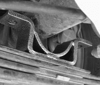
Place the new axle locator bracket on top of the spring, off-center hole toward the front -
Install new U-bolts and spring plates (5 hole) on the bottom of the springs. Cross-torque the u-bolts.
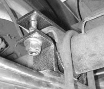
Install new U-bolts and spring plates; cross-torque u-bolts -
Place the new upper axle plates with the pin down on top of the axle. From the 5/8" bolts included, choose the appropriate length bolts. Install and tighten the 5/8" bolts provided with one flat washer on top of the upper plate and one on the bottom of the axle locator.
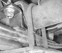
Place the new upper axle plates with the pin down on top of the axle


Installing Frame Supports
Frame supports are installed after the axle is relocated. Raise the axle, and mark the center on the frame. Use this mark to center the frame support. Make a template or use one of the brackets and mark the frame. Use a sawzall, cutting wheel, or plasma cutter to notch the frame. Do not use a torch!! Move any wires or brake lines out of the way before cutting. Drill and bolt the frame support to the frame. Install the bump stop to the frame support.

Raise the carrier bearing to correct the drive line angle. See the CB99 instructions below.
Install new rear shocks. Use 1700 (shorter shock) on the driver side and 1800 (longer shock) on the passenger side.
After raising the carrier bearing, test drive and adjust pinion angle as necessary.
Refer to the checklist on the Installation Helper and complete the installation. Measure and record the completed height.
After the installation is complete and all adjustments to drive line are made, DJM recommends welding the axle bracket to the factory axle tube. Before welding, make sure the pinion angle is correct and there is no vibration in the drive line.
PART # CB99
Carrier Bearing Bracket
1999-2006 Chevy 1500 & 2001-2010 Chevy HD
Installation Instructions
Rev. # 5-02

Please take the time to read these installation instructions and check the Hardware Parts List to be sure you have all the listed parts.
These installation instructions are prepared for the professional installer with the proper equipment, tools and experience in suspension systems and safety.
Hardware Parts List
| 1 | Carrier bearing bracket |
| 2 | 3/8" x 3-1/2" bolts w/ nuts and washers |
Vehicles with 2-piece drive shafts may experience drive line vibration at low speeds and will need to raise the carrier bearing.
- The bearing is welded to a round cross member and will need to be cut off and moved up.
-
Cut the stock bracket off the cross member. Place the new bracket on the carrier bearing and position it on the cross member at the new location. Mark the center of the slotted hole and drill through the cross member with a 3/8" bit.
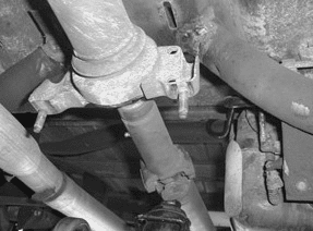
Position the bracket on the cross member and drill through with a 3/8" bit -
Bolt the bracket to the cross member and to the carrier bearing and tighten. You can adjust the bracket up or down if needed.
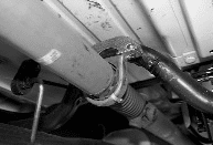
Bolt bracket to cross member and carrier bearing and tighten