1999-2006 Chevy/GMC Silverado 3 inch Front / 4 inch Rear Complete Lowering Kit (Shocks Included)
$973.28
Lower your 1999–2006 Chevy/GMC Silverado or Sierra with DJM Suspension’s complete truck lowering kit, featuring a 3-inch front drop and 4-inch rear drop. The kit includes lowering control arms, rear hangers and shackles, and shocks.
Looking for a 2003 or 2005 Silverado lowering kit? DJM Suspension offers a complete 3/4 drop solution for compatible 1999-2006 Chevy/GMC Silverado and Sierra trucks. It includes front lowering control arms, a rear hanger and shackle kit, shocks, and a passenger-side rear shock extender.
- 3-inch front lowering control arms
- 4-inch rear hanger and shackle kit
- Front and rear shocks included
Description
Recommended Paired & Replacement Parts
Keep your lowered Silverado's suspension in good condition with compatible shocks and replacement components. DJM Suspension recommends the following parts for your 3/4 lowering kit.
Recommended Shocks
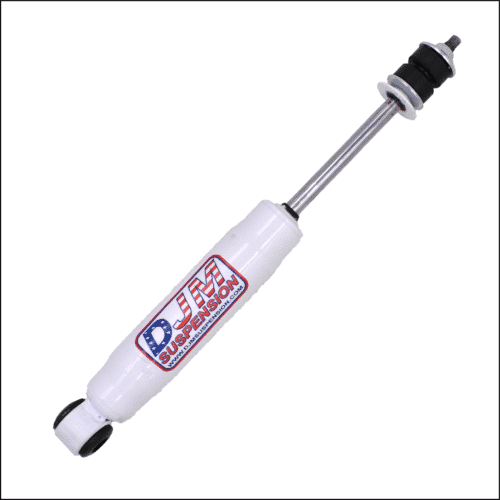
- Front Shock: 14.5" Stem/Loop SuperShock 1415 (sold each)
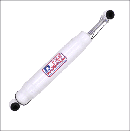
- Rear Driver-Side Shock: 19.5" Loop/Loop SuperShock 1900 (sold each)
- Rear Passenger-Side Shock: 20.5" Loop/Loop SuperShock 2000 (sold each)
Replacement Parts
Why Buy from DJM Suspension
Decades of Suspension Expertise
With suspension experience dating back to the early 1970s, DJM Suspension develops lowering components for drivers customizing their cars and trucks.
American-Made Suspension Products
Choose truck lowering kits from a family-owned American manufacturer with decades of experience in aftermarket suspension products for cars and trucks.
Designed for Vehicle-Specific Lowering
DJM Suspension develops lowering components tailored to specific vehicle applications, helping truck owners find suspension solutions suited to their vehicle and desired ride height.
About DJM Suspension
DJM Suspension is a family-owned and operated American manufacturer with roots in Southern California's aftermarket automotive community. Since the early 1970s, we've developed suspension solutions for drivers who love customizing their vehicles. From classic trucks to modern pickups, our lowering products reflect decades of industry knowledge and a passion for achieving the perfect stance.
Frequently Asked Questions
Get the Complete Silverado Lowering Kit
Shop the 3-inch front and 4-inch rear lowering kit for compatible 1999–2006 Chevy/GMC Silverado and Sierra trucks.
Additional information
1999-2006 (2007 Classic) Silverado/Sierra 3 inch Front Lowering Control Arms
| Weight | 45 lbs |
|---|
1999-2006 Chevy/GMC Silverado 4 inch Rear Lowering Kit
| Weight | 20 lbs |
|---|
14.5″ Stem / Loop SuperShock (1415)
| Weight | 3 lbs |
|---|
19.5″ Loop / Loop SuperShock (1900)
| Weight | 3 lbs |
|---|
20.5″ Loop/Loop SuperShock (2000)
| Weight | 3 lbs |
|---|
Part # CA2599L-2, CA2599L-4 & CA2599L-5
1999–2006 Chevy C1500 Pickup Lower Control Arms
Installation Instructions
Rev. # 05-02

Please take the time to read these INSTALLATION INSTRUCTIONS and check the Hardware Parts List to be sure you have all the listed parts.
DJM parts should be installed by qualified mechanics. If you are not familiar with automotive repair, have the parts installed by someone with experience.
Please read the warranty information (blue page enclosed). Complete your Product Warranty Card and mail it to DJM Suspension.
Please take a few minutes to fill out your installation helper (back side of warranty). Accurate measurements BEFORE BEGINNING INSTALLATION will show any irregularities in your vehicle.
NEVER WORK UNDER TRUCK SUPPORTED BY A JACK ONLY!!! USE QUALITY JACK STANDS WHICH HAVE A RATING ADEQUATE FOR YOUR TRUCK'S WEIGHT!!!
THIS KIT IS DESIGNED TO BE USED WITH THE FACTORY COIL SPRINGS. USING AFTERMARKET COIL SPRINGS OR AIR BAGS WILL VOID DJM'S WARRANTY!!
CA2599L-5 requires upper control arm DJM #CA2599U, sold separately. CA2599L-5 WILL NOT WORK WITH FACTORY WHEELS AND TIRES!!
INSTALLER MUST CHECK THAT THERE IS ABSOLUTELY NO CLEARANCE PROBLEMS BETWEEN THE WHEELS, THE SPINDLE, THE CALIPER, THE LOWER CONTROL ARMS AND ANY OTHER COMPONENT BEFORE DRIVING VEHICLE.
Hardware Parts List
| 1 – Left Lower Control Arm | 6 – Grease Fittings |
| 1 – Right Lower Control Arm | 2 – Ball Joints (Installed, 6541) |
| 8 – Pivot Bushings (Installed) | 2 – Sway Bar End Links |
| 1 – Set Twin Tube Sleeves | 1 – Tube Loctite |
| 4 – 16m Nylock Nuts |
-
This kit uses DJM's twin tube pivot sleeves. YOU MUST ASSEMBLE THESE SLEEVES CORRECTLY. DO NOT SKIP THIS STEP!!
The sleeves are already installed in the control arms. Cut the zip tie holding the nut and inner sleeve. Remove the inner sleeve and set both aside. A small hole is drilled for the grease to pass through to the inner sleeve. Although this is done at the factory, check that there is a 1/8" hole drilled through the zerk fitting hole into the bushing and outer sleeve (Fig. 1). The drilling operation will leave a burr on the inside of the sleeve, and it must be removed. Use a rat tail file to completely remove all burrs from drilling and on the ends of the sleeves (Fig. 2). Make sure you clean out any chips or dirt. Install grease fittings (Fig. 3).
With the outer sleeves drilled and cleaned, it is important to check the inner sleeves. These sleeves should be about .050" longer than the outer sleeve. Assemble them before greasing to check that the length is slightly longer and that they rotate smoothly. Now apply some grease to the inner sleeve and insert it into the control arm (Fig. 4). Install the ball joint grease fitting (Fig. 5).
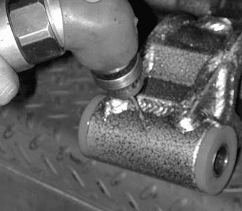
Fig. 1 – Check the 1/8" grease hole 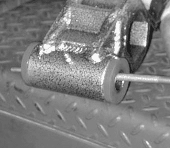
Fig. 2 – Remove all burrs with a rat tail file 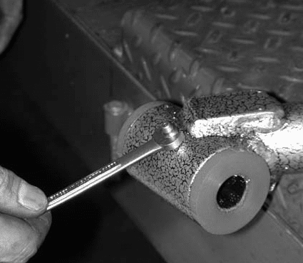
Fig. 3 – Install grease fittings 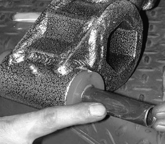
Fig. 4 – Insert greased inner sleeve 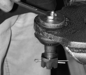
Fig. 5 – Install ball joint grease fitting -
Do not impact the pivot bolts. Clean bolts before installing. Replace factory nuts with the nylock nuts provided with the kit. Tighten to 30 lbs.
-
Before installing the sway bar end links, loosen the four 10mm bolts that hold the D-bushings to the frame. Install the sway bar end links. You may need to raise the arm with a floor jack a little. DO NOT OVER TIGHTEN END LINKS!! 2 OR 3 THREADS PAST THE LOCK NUT IS ALL YOU NEED. Cycle the suspension to seat the sway bar and tighten the D-bushings. Review all procedures and check that all parts are tight and installed correctly.
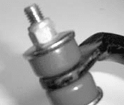
Correct – about 2–3 threads past the nylock nut 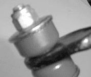
Incorrect – too many threads past the nut; this bolt is over-tightened -
Replace wheels and torque lug nuts. Check that the tires will turn both ways without making contact. INSTALLER MUST CHECK THAT THERE IS ABSOLUTELY NO CLEARANCE PROBLEMS BETWEEN THE WHEELS AND TIRES, THE SPINDLE, THE CALIPER, THE CONTROL ARMS OR ANY OTHER COMPONENT BEFORE DRIVING VEHICLE.
-
To get the toe close, turn the tie rod ends in about 3 full turns. Turn your steering wheel until it is straight. By sighting down the tires and truck, you can get the toe fairly close. Adjustment is made with the tie rod ends. Loosen the nuts at the rack and turn the tie rod ends until the tires are in a straight line from front to rear. Close is all you need; your alignment shop will correct this for you. Don't forget to tighten the nuts. TAKE YOUR TRUCK TO A QUALIFIED ALIGNMENT SHOP FOR A PROFESSIONAL ALIGNMENT. ALIGN TO FACTORY SPECS.
-
With the vehicle on the ground, measure the front height and record it on the installation helper. Your measurements should be about 2-1/2" (CA2599L-2), 3-1/2" (CA2599L-4) and 4-1/2" (CA2599L-5) less than the before measurement. REMEMBER: AFTER TEST DRIVING, INSPECT INSTALLATION AND DOUBLE CHECK ALL THE HARDWARE IS TIGHT.


Part # HS2599-4 & HS2599-4X
1999–2006 Chevy C1500 Rear Hangers & Shackles
Installation Instructions
Rev. # 3-03

Please take the time to read these INSTALLATION INSTRUCTIONS and check the Hardware Parts List to be sure you have all the listed parts.
DJM parts should be installed by qualified mechanics. If you are not familiar with automotive repair, have the parts installed by someone with experience.
Please read the warranty information (blue page enclosed). Complete your Product Warranty Card and mail it to DJM Suspension.
Please take a few minutes to fill out your installation helper (back side of warranty). Accurate measurements BEFORE BEGINNING INSTALLATION will show any irregularities in your vehicle.
NEVER WORK UNDER TRUCK SUPPORTED BY A JACK ONLY!!! USE QUALITY JACK STANDS WHICH HAVE A RATING ADEQUATE FOR YOUR TRUCK'S WEIGHT!!!
Compare hanger to original before beginning. If mounting is different than stock, call DJM for assistance.
Hardware Parts List
| 2 – Spring Eye Hangers | 2 – Bump Stops (10S) |
| 2 – Shackles w/ Bushings (1011) | 1 – Shock Extender (2599) |
| 8 – 7/16" x 14 Nylock Nuts | 2 – 1/2" x 20 x 1" Bolts |
| 8 – 7/16" x 14 x 1-1/4" Bolts | 2 – 1/2" x 20 Jam Nuts |
| 8 – 7/16" Flat Washers | 1 – 1/2" x 13 x 2-3/4" Bolt |
| 2 – 5/8" x 11 x 4-1/2" Leaf Spring Bolts | 1 – 1/2" x 13 Nylock Nut |
| 2 – 5/8" Flat Washers | 1 – 3/8" x 16 x 1" Bolt |
| 2 – 5/8" x 11 Nylock Nuts | 1 – 3/8" x 16 Nylock Nut |
| 1 – Carrier Bearing Bracket Kit (CB99) (HS2599-4X only) | |
-
Remove rear shocks. Keep hardware. Position a floor jack under the center of the rear axle and raise it until the weight is taken off the leaf springs. Remove the bolt holding the front of the leaf spring to the front spring hanger. Loosen and remove the two shackle bolts, and remove the stock shackle.
Caution: Leaf springs are under considerable tension. Good judgment should be used when removing shackle bolts. The rear spring may move, causing a pinch point between the spring and rear shackle.
-
Remove the rivets holding the spring hanger to the frame. This can be done with an air chisel or by drilling out the rivets. With the new bolts supplied, attach the spring to the hanger and install nuts. Do not tighten nuts. Mount your new DJM spring hanger in the original holes on the frame with the hardware provided, and torque bolts to 55–60 ft/lb. The gas tank will need to be moved to gain access to the bolts on the driver side.
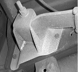
New spring hanger mounted to frame 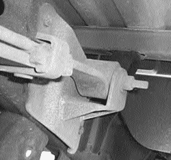
Spring attached to new hanger -
Apply some grease to the bushings and inside sleeves, then attach the new shackle to the frame mount and bolt it in place with the factory bolts (Fig. 1). The shackle installs with the bushings down and the open side forward. The hole farthest from the bushing will lower the truck more than the closer hole. Now raise the rear axle high enough to align the spring eye and shackle. Insert the remaining bolt and install nuts.
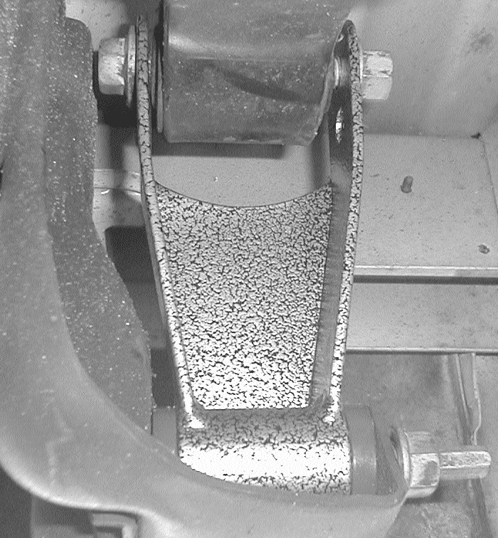
Fig. 1 – Shackle installed, bushings down -
Remove the stock bump stop and replace it with the new shorter stop.
-
Before installing the rear shocks, install the shock extender to the right side axle mount. This will make the shock work at a much better angle. Slide the bracket over the factory mount, install the two 1/2" x 1" bolts from the outside and tighten (Fig. 2). Then line drill a 3/8" hole through the factory mount using the shock extender as a guide, install the 3/8" x 1" bolt and tighten. Now install the DJM #1900 rear shock on the driver side and the DJM #2000 on the passenger side.
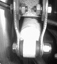
Fig. 2 – Shock extender installed -
Install rear wheels and torque lug nuts. Remove the jack stand and floor jack. Check the height of the rear. You can change the height by moving the spring to the other hole in the shackle. When satisfied with the height, torque all bolts to factory specs.
-
Take the truck for a test drive. If drive line vibration occurs with 2-piece drive shafts, install the carrier bearing bracket #CB99 (included with HS2599-4X) to correct the drive line angle. Remove the factory bracket from the cross member, then position the new bracket and drill two holes to attach it. Check all bolts for correct torque.
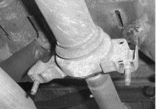
Remove factory bracket from cross member 
Position new bracket and drill two holes to attach