


1988-1998 Chevy/GMC C-1500 4inch front/6inch rear Lowering Kit (with upper control arms) (Shocks Included)
$1,337.58
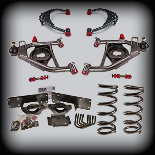
Give your C-1500 a dramatic, factory-clean drop with this complete Chevy/GMC C1500 lowering kit, built with new control arms, springs, and a fully adjustable rear flip kit for a smooth, aggressive stance.
This C1500 4/6 drop kit combines new upper and lower control arms with 2-inch drop coil springs up front and a 6-inch rear axle flip kit. The kit also includes the applicable ball joints, bushings, shocks, C-notch, shock extenders, and installation hardware.
- 4 Inch Front / 6 Inch Rear Drop
- Upper & Lower Control Arms + 2-Inch Drop Springs
- Shocks, C-Notch, Shock Extenders & Hardware Included
- Description
- Additional information
- Lower Control Arm Instructions
- Upper Control Arm Instructions
- Front Coil Springs Instructions
- Rear Flip Kit Instructions
Description
Recommended & Replacement Parts
Round out your build with these matched components, or keep your kit running strong with genuine replacement parts.
DJM Recommends:
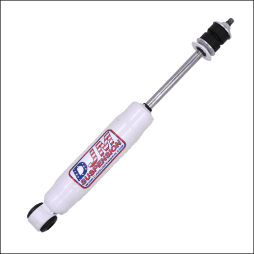
- 13.5″ Stem / Loop SuperShock (1315) — Front Shock (sold each)
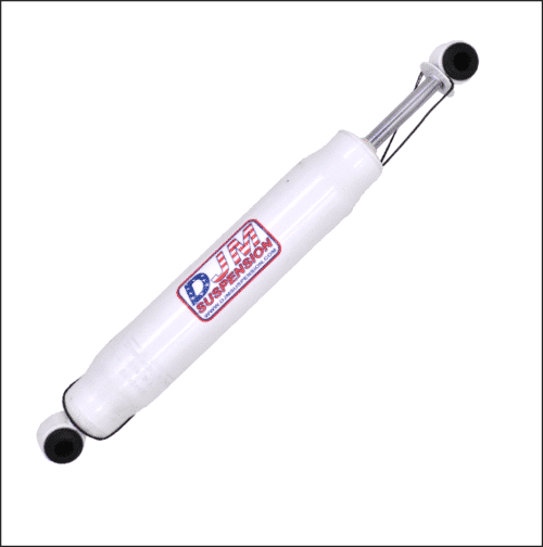
- 20.5″ Loop / Loop SuperShock (2000) — Rear Driver's Shock (sold each)
- 22.5″ Loop / Loop SuperShock (2200) — Rear Passenger's Shock (sold each)
Note: The shocks listed above are included with this lowering kit. Individual shocks are also available separately as replacement parts.
Replacement Parts
- Upper Ball Joint (6370)
- Lower Ball Joint (6293)
- 1988-1998 DJM Upper Control Arm Bushing Replacement Kit
- Replacement Bushing kits for Calmax Control Arms (BK2555L)
Why Buy from DJM Suspension
Decades of Lowering Experience
DJM Suspension has been manufacturing suspension and lowering components since the early 1970s, with products designed for a range of truck applications.
Complete Suspension Solutions
This C-1500 lowering kit combines the major front and rear suspension components needed for the specified 4-inch front and 6-inch rear drop.
Application-Specific Components
The kit is designed specifically for 1988-1998 Chevy/GMC C-1500 applications and combines components matched to the 4/6 drop configuration.
About DJM Suspension
Aftermarket automotive passion is what started DJM Suspension, and it's still what drives us today. We're a family-owned, American-made manufacturer that's trusted by truck owners since the early 1970's, engineering suspension parts trusted by truck owners who expect their ride to perform as sharp as it looks.
Frequently Asked Questions
Get the Drop Your C1500 Deserves
Complete your installation with a Chevy/GMC C1500 lowering kit engineered for a clean stance, smooth ride, and lasting strength.
Additional information
1988-1998 C1500 Silverado/Sierra 4 inch Lowering Control Arms
| Weight | 45 lbs |
|---|
1988-1999 C1500 Silverado/Sierra 2 inch drop coil springs
| Weight | 30 lbs |
|---|
1988-1998 C1500 Silverado/Sierra Upper Control Arms
| Weight | 20 lbs |
|---|
1988–1998 Chevy C1500 6 inch Rear Leaf Spring Axle Flip Kit
| Weight | 50 lbs |
|---|
13.5″ Stem / Loop SuperShock (1315)
| Weight | 3 lbs |
|---|
20.5″ Loop/Loop SuperShock (2000)
| Weight | 3 lbs |
|---|
22.5″ Loop/ Loop SuperShock (2200)
| Weight | 3 lbs |
|---|
1988–1998 Chevy C1500 4" Control Arms
Safety First
Always work on a flat, level surface with the vehicle supported on properly rated jack stands. Never work under a vehicle supported only by a jack. Coil springs store a large amount of energy and can cause serious injury or death if released unexpectedly. Use a proper spring compressor or controlled jack method, and keep all people clear of the spring at all times.
Installation of suspension components should be performed by a qualified technician. If you are unsure about any step, contact DJM tech support before proceeding.
Installation Video
A complete installation video for this kit is available. Visit djmsuspension.com or scan the QR code on the printed instruction sheet.
Kit Components
| Part # | Description |
|---|---|
| CA2555U | Upper control arms (upper ball joints and grease fittings installed by customer) |
| CA2555L-4 | 4" lower control arms (lower ball joints factory installed; grease fittings installed by customer) |
Installation
-
Install Ball Joints and Grease Fittings
Install the upper ball joints and grease fittings into the upper control arms. The lower ball joints are installed at the factory, so only the grease fittings need to be installed on the lower arms.
-
Grease the Control Arms
Lube all fittings. Make sure grease flows through the predrilled grease holes, grease fittings and twin sleeves, and that the arms pivot smoothly.
Note: If a fitting will not accept grease, correct it before the arms go on the truck. It is much harder to fix once installed. -
Trim the Upper Spring Tower (If Needed)
The driver's side upper spring tower may need to be trimmed to make spring installation easier. Only 1/4" of extra clearance is needed.
Note: Remove only what is necessary and deburr and paint any trimmed edges to prevent rust. -
Install the Control Arms and Coil Springs
Install the control arms and coil springs.
Critical: Use extreme caution when compressing coil springs. Make sure everyone is out of the way and clear of the spring before and during compression. Never place hands or any body part between the coils or in the spring's path. -
Install the Shock and Remove the Jack
With the coil spring compressed and in position, install the shock. Once the shock is installed, you will be able to remove the jack.
-
Position the Tie Rod Sleeves
Rotate the tie rod sleeves so the clamp bolt heads point away from the bump stops. Confirm there is no contact between the bolts and the bump stops.
Note: Turn the steering fully lock to lock and cycle the suspension to confirm clearance through the full range of travel.
After Installation
A professional front-end alignment is required after installation. Check clearance between the tires, control arms, brake lines and frame through full steering and suspension travel. Re-check all fastener torque after the first 50–100 miles, and grease the fittings as part of regular maintenance.
Warranty
DJM Suspension products are warranted against defects in materials and workmanship. This warranty does not cover improper installation, misuse, modification, racing or off-road use, or normal wear. Contact DJM Suspension with your order information for warranty claims.
Chevy Silverado / GMC Sierra Upper Control Arms
Safety First
Always work on a flat, level surface with the vehicle supported on properly rated jack stands. Never work under a vehicle supported only by a jack. Support the lower control arm before removing the upper control arm or ball joint, because the coil spring is under load.
Installation of suspension components should be performed by a qualified technician. If you are unsure about any step, contact DJM tech support before proceeding.
Applications
| Part # | Application | Ball Joint |
|---|---|---|
| CA2555U | 1988–1998 C1500 Silverado / Sierra | K6292 (Moog) |
| 2599UXL | 1999–2006 Silverado / Sierra, custom upper arms for extreme drops (5"+) | K6136 |
| CA2515U | 2015–2018 Silverado / Sierra | K6292 (DJM) |
| CA2519U | 2019–2024 Silverado / Sierra | K6292 (DJM) |
Installation
-
Bolt In the Ball Joint
CA2555U & 2599UXLBolt the ball joint to the control arm as shown on the printed sheet and tighten to 60 ft-lbs.
-
Install the Grease Fittings
All modelsInstall the grease fittings into the predrilled twin tube sleeves and, if equipped, the ball joint.
-
Pre-Grease the Twin Sleeves and Ball Joint
All modelsPre-grease the twin sleeves to confirm the predrilled holes are clear and grease flows smoothly.
If the ball joint is greaseable, grease it now. If it is maintenance-free (no grease fitting), no action is needed.
Note: If a sleeve will not accept grease, correct it before the arm goes on the truck. -
Deburr the Upper Ball Joint Taper
2016–2018 steel knuckle onlySteel knuckles on these years have a small burr on the upper ball joint taper. Remove it with a file or die grinder, then test fit the upper ball joint to make sure there is no interference.
Critical: The ball joint stud must seat fully in the taper. A stud that doesn't seat fully can loosen in service and lead to ball joint separation and loss of steering control. Remove only the burr and do not enlarge the taper. -
Install the Control Arms
All modelsInstall the upper control arms on the vehicle.
-
Secure the Brake Line
CA2515U & CA2519U: Install the brake line bracket on the control arm and route the brake line through it.
CA2555U & 2599UXL: Secure the brake line to the control arm with the zip ties provided.
Critical: Turn the steering fully lock to lock and cycle the suspension to confirm the brake line is not stretched, pinched or rubbing at any point. A damaged brake line can cause brake failure. -
Align the Vehicle
All modelsHave the vehicle aligned to factory specifications.
After Installation
Check clearance between the tires, control arms, brake lines and frame through full steering and suspension travel. Re-check all fastener torque after the first 50–100 miles, and grease the fittings as part of regular maintenance.
Warranty
DJM Suspension products are warranted against defects in materials and workmanship. This warranty does not cover improper installation, misuse, modification, racing or off-road use, or normal wear. Contact DJM Suspension with your order information for warranty claims.
Front Coil Springs
Safety First
Never work under a truck supported by a jack only. Use quality jack stands rated for your truck's weight, on a flat, level surface.
Coil springs store a large amount of energy and can cause serious injury or death if released unexpectedly. Lower and raise the control arm slowly and keep all people clear of the spring at all times.
Installation of suspension components should be performed by a qualified technician. If you are unsure about any step, contact DJM tech support before proceeding.
New Front Shocks Required
New front shocks are always required when installing lowered coil springs. Refer to the application chart for the correct part number.
Before You Begin
Read these instructions completely and check the parts list below to make sure you have all listed parts and the tools needed to complete the installation safely.
Take ride height measurements at all four corners before starting. Accurate measurements before installation will show any side-to-side irregularities in your vehicle. Also review the warranty information included with your kit.
Parts List
| Qty | Description |
|---|---|
| 2 | Front coil springs |
| 2 | Tall bump stops (as required) |
Installation
-
Raise and Support the Truck
Park the truck on a flat, level surface and chock the rear wheels. Loosen the front lug nuts, raise the front with a floor jack and support the frame with jack stands. Remove the front wheels.
Critical: Always use jack stands. Never rely on a jack alone. -
Remove the Shock, Tie Rod End and Sway Bar Links
Remove the front shock. Remove the cotter pin and nut from the tie rod end, then remove the tie rod end from the spindle. Loosen and remove the sway bar end links (if equipped).
-
Loosen the Lower Ball Joint
Working on one side at a time, place a floor jack under the lower control arm. Remove the cotter pin and loosen the lower ball joint nut. Tap the spindle to break the taper loose, then remove the nut.
Critical: The floor jack must be supporting the lower control arm before the ball joint is separated. The coil spring is holding the arm under load. -
Remove the Stock Coil Spring
Slowly lower the floor jack until the ball joint comes out of the spindle. Swing the spindle out of the way, then continue lowering the jack slowly until the stock coil spring can be removed.
Note: Be careful not to tear the rubber pad (if equipped). It gets reused on the new spring. -
Install the New Coil Spring
Place the rubber pad (if equipped) on the same end of the new spring. Set the new spring into the lower control arm, holding the top of the spring straight. Slowly raise the lower control arm with the floor jack until the ball joint lines up with the spindle hole and the spring is seated in both the upper and lower mounts.
Note: The spring may need to be turned while raising the floor jack to seat it properly. -
Reconnect the Ball Joint and Tie Rod End
Install and tighten the ball joint nut. Install the tie rod end into the spindle and tighten its nut. Install new cotter pins in both the ball joint and the tie rod end.
Critical: Always use new cotter pins. Never reuse old ones. -
Reinstall the Sway Bar Link and Install the New Shock
Attach the sway bar end link to the lower control arm and install the new front shock.
-
Repeat on the Other Side
Repeat steps 3 through 7 on the other side of the vehicle.
-
Install the Wheels
Install the wheels and torque the lug nuts to factory specification.
-
Test Drive and Align
Take the vehicle for a test drive, then have the front end aligned at a qualified alignment shop.
After Installation
Check clearance between the tires, control arms, brake lines and frame through full steering and suspension travel. Re-check all fastener and lug nut torque after the first 50–100 miles.
Warranty
DJM Suspension products are warranted against defects in materials and workmanship. This warranty does not cover improper installation, misuse, modification, racing or off-road use, or normal wear. Contact DJM Suspension with your order information for warranty claims.
1988–1998 Chevy 1500 Rear Flip Kit
Safety First
Never work under a truck supported by a jack only. Use quality jack stands rated for your truck's weight, on a flat, level surface.
These instructions are written for a professional installer with the proper equipment, tools and experience in suspension systems and safety. This vehicle and its components are extremely heavy and can be dangerous without the proper equipment and experience. If you are unsure about any step, contact DJM tech support before proceeding.
Two Wheel Drive Only
Unless specifically stated, all DJM lowering components are intended exclusively for two wheel drive applications.
New Shocks Required
New rear shocks are required. Use #2000 on the driver side and #2200 on the passenger side.
Before You Begin
Read these instructions completely and check the parts list below to make sure you have all listed parts.
Take ride height measurements at all four corners before starting. Accurate measurements before installation will show any irregularities in your vehicle. Also review the warranty information included with your kit.
Parts List
| Qty | Description |
|---|---|
| 2 | Axle locators (1010-A) |
| 2 | Upper axle plates (1010-P) |
| 4 | 5/8" U-bolts (1025) |
| 8 | 5/8" x 18 Nylock nuts |
| 8 | 5/8" flat washers |
| 2 | 5/8" x 11 x 3-1/2" tap bolts |
| 2 | 5/8" x 11 x 4" tap bolts |
| 8 | 5/8" flat washers |
| 8 | 5/8" x 11 Nylock nuts |
| 2 | Leaf spring plates (1025) |
| Qty | Description |
|---|---|
| 1 | Left frame support (1025) |
| 1 | Right frame support (1025) |
| 16 | 1/2" x 13 x 1.75" bolts |
| 16 | 1/2" flat washers |
| 16 | 1/2" x 13 Nylock nuts |
| 2 | Bump stops (10S) |
| Qty | Description |
|---|---|
| 2 | Shock extenders (1125) |
| 2 | 3/8" x 16 x 1" bolts |
| 2 | 3/8" x 16 Nylock nuts |
| 2 | 3/8" flat washers |
| 2 | 1/2" x 13 x 2.75" bolts |
| 4 | 1/2" x 20 x 1" bolts |
| 4 | 1/2" x 20 jam nuts |
| 4 | 1/2" flat washers |
| 2 | 1/2" x 13 Nylock nuts |
| 8 | 1/2" lock washers |
| Qty | Description |
|---|---|
| 2 | 3/8" shim plates |
| 2 | 3/8" x 16 x 2-1/4" bolts |
| 2 | 3/8" x 16 Nylock nuts |
| 4 | 3/8" flat washers |
Relocating (Flipping) the Rear Axle
-
Remove the Leaf Springs
With the frame on jack stands and the rear axle supported, remove the front and rear spring eye bolts and remove the springs from the truck. Keep the bolts, because they are reused to reinstall the springs.
Critical: The rear axle must be supported by a jack or stands before the spring eye bolts are removed. The axle is extremely heavy and will drop once the springs are disconnected. -
Reinstall the Springs Under the Axle
Reinstall the leaf springs under the axle using the original spring eye bolts.
-
Install the Axle Locators
Place the new axle locator bracket on top of each spring with the off-center hole toward the front of the vehicle. This centers the rear axle and pulls the drive shaft back slightly from the transmission.
-
Lower the Axle and Set Pinion Angle
Lower the rear axle into the new axle supports. Rotate the axle to the desired pinion angle.
-
Install the U-Bolts and Spring Plates
Install the new U-bolts and 5-hole spring plates on the bottom of the springs. Tighten the U-bolts in a cross pattern.
Note: Do not overtighten the U-bolts. Overtightening can bend the spring plates. -
Install the Upper Axle Plates
Place the new upper axle plates on top of the axle with the pin facing down. Install the 5/8" x 3-1/2" bolt in the forward position and the 5/8" x 4" bolt in the rear, with one flat washer on top of the upper plate and one on the bottom of the axle locator.
Installing the Frame Supports
-
Mark the Frame
Frame supports are installed after the axle is relocated. Raise the axle and mark its center on the frame. Use this mark to center the frame support.
The frame supports mount with the long side forward. Make a template, or use one of the brackets, to mark the frame for notching.
-
Notch the Frame
Move any wires or brake lines out of the way, then notch the frame with a Sawzall, cutting wheel or plasma cutter.
Critical: Do not use a torch to notch the frame. Always move wiring, brake lines and fuel lines clear of the cut area before cutting, and keep a fire extinguisher nearby. -
Install the Frame Supports and Bump Stops
Drill and bolt each frame support to the frame, then install the bump stops on the frame supports.
Installing the Shock Extenders
-
Mount the Shock Extenders
Mount the new shock extenders to the original lower shock mounts. The new shock installs out and down from the original mount, with the wide end of the extender mounted to the original mount.
Line up each extender with the original shock holes and attach it with two 1/2" x 1" bolts in the original holes, nuts on the inside.
-
Drill and Secure the Extenders
Using the shock extender as a template, drill a 3/8" hole through the original mount. Secure with a 3/8" x 1" bolt, washer and nut.
-
Install the New Shocks
Install the new shocks to the shock extenders with the 1/2" x 13 x 2.75" bolts and tighten.
Final Checks
-
Test Drive
Take the truck for a test drive and check for driveline vibration.
-
Install the Carrier Bearing Shims (If Needed)
FK1025-X with 2-piece drive shaftsIf driveline vibration occurs, raise the carrier bearing and install the shims between the bearing and the cross member. Attach with the new bolts.
-
Adjust Pinion Angle and Record Ride Height
Adjust the pinion angle as necessary. Measure the completed ride height and compare it to your measurements from before the installation.
After Installation
Check clearance between the tires, springs, axle, brake lines, exhaust and fuel tank through full suspension travel. Re-check U-bolt and all fastener torque after the first 50–100 miles, and periodically after that.
Warranty
DJM Suspension products are warranted against defects in materials and workmanship. This warranty does not cover improper installation, misuse, modification, racing or off-road use, or normal wear. Contact DJM Suspension with your order information for warranty claims.